Antec NSK1300 with PW-200-V DC-DC and Akasa Evo-120
Posted: Sat Mar 03, 2007 12:31 am
Plot Synopsis:
My wife's Linux box needed an upgrade. She's had a Shuttle, and likes the small size, but I (being her system vendor) don't like that Shuttle's chassis are throwaway (i.e. motherboard cannot be replaced). So, with some inspiration from Bluefront, I've tried building a simple system in an Antec NSK1300. I'm less skilled/patient/industrious than Bluefront, whose case is an Antec Aria, kind of like Mark Martin's car is a Chevy Monte Carlo. So I tried to get 75% of the benefit with 15% of the effort. The rough plan was to discard the stock PSU from the NSK1300, put a 120mm fan in its place, and power the system using an external power-brick and an efficient DC-DC converter. In case any of this is helpful to anyone who might be itching to build a reasonably quiet SFF desktop, here's what I did...
Cast of Characters:
Mobo : ASUS P5B-VM
CPU : C2D E6300 (I should have opted for the E6600)
HDD : Hitachi 7K100 (2.5" 7200rpm)
CDRW : some old Lite-On
Case : Antec NSK1300 with stock PSU removed
CPU HS : Akasa Evo-120 (AK-920)
AC/DC : Dell 220W external brick power adapter ($40 via eBay)
DC/DC : Mini-Box PW-200-V DC/DC converter
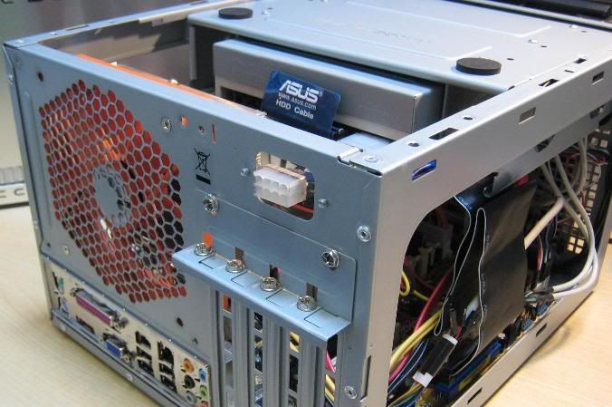
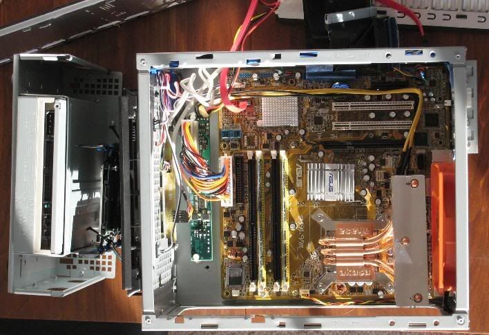
Right now the onboard VGA drives a 1600x1200 CRT, but at some point we'll add a low-power 2x DVI graphics card, to run a pair of 1600x1200 LCDs (her work is all 2-D, but lots of pixels is nice). So I wanted more power headroom than I'd have from a 120W picoPSU. Mini-Box offer their 200W DC/DC design on either a square-ish PCB (PW-200-M) or a long skinny PCB (PW-200-V). Plugged directly into the ATX power connector on the P5B-VM, neither of these would fit in the case. (This is not strictly true, as I'll confess later). Bluefront has a shorter than normal mATX motherboard in his Aria, which is why he has plenty of room for his PW-200-M. So I mounted the PW-200-V upside-down in front of the mobo, and used a generic 20pin-24pin ATX adapter cable to connect it.
To mount the DC/DC, I found 3/8 x 2 inch hex-head nylon cap screws at a hardware store. Cut off the end, drilled and 6-32 tapped through the axis, and filed the shoulder of one of them to provide clearance for a capacitor at the end of the PW-200-V. I drilled a couple of holes in the floor of the case, and used 6-32 x 3/8 machine screws to fasten the nylon pillars to the base. The pillars provide a sturdy mounting, and are non-conductive -- the PW-200-V's mounting holes are perilously near to exposed 12V wires.
Various threads (e.g. 28246,29018) have discussed modding the Dell 150W or 220W AC/DC adapters for use with DC/DC desktops. I'd rather not burn my house down, so I opened my brick and traced out enough of the DC end of the circuit to convince myself that the adapter does work as simply as the various forum posts suggest. Dell has multiple sources for these 220W bricks. Most people mention Delta. Mine happens to be made by HiPro (ZVC220HD12S1). The Dell end of it should be the same, regardless of the manufacturer. The cable is 8 conductor, though pin 1 is unused.
The pinout, numbered as in the picture, is:
1: N/C. Soldered to a through-hole in the adapter's PCB, but that through-hole is not connected to anything else on the PCB.
2,3,4 : +12V. Three white wires to carry the outbound current. Two meters of 16 gauge copper is about 24 mOhm, and 18 Amps through that would be about a 425 mV drop, so this adapter triples the wire, dividing the drop by three (i.e. 142 mV at max current). The three wires solder together into one big hole in the adapter's PCB.
Pin 5 : 'Trigger.' There's a pullup resistor in the brick which causes this signal to float up to a few volts. Short this line to ground, and the adapter goes from Standby (amber LED) to On (green LED).
Pins 6,7,8 : Ground. Three black 16g wires. They have to carry all that 18 A current back to the adapter, so unfortunately, this means that 'ground' inside this PC is up to 142 mV higher potential than earth. All three are soldered together into one hole in the adapter's PCB ground plane.
Aside: The adapter's PCB ground plane is then directly connected to the earth pin of the AC mains connector. Thus the 142 mV 'ground' on my mobo could create issues if I had an external (e.g. USB) peripheral that powered by a power adapter with three-wire mains that was similarly connected. I could wind up dumping quite a lot of current through the shield on a USB cable. Perhaps I shouldn't be surprised to see this, in cost-sensitive consumer commodity designs (i.e. a Dell laptop), but it's something to keep in mind when using this type of setup.
The PW-200-V came with 12 inch power input leads (18 gauge wire!) terminated with a 5mm barrel connector socket. Most users who've posted on these forums have gone to Radio Shack etc and found a plug to fit it. However, barrel connectors like this are generally rated for less than one amp. I opted to keep the Dell power-brick and it's connector intact, and find a mating connector. I desoldered the 24-pin ATX power socket from an old ATX motherboard. I cut it in two (leaving only positions 1-4 & 13-16), to make myself an 8-pin connector which mates perfectly with the connector on the Dell brick. These Molex connectors are rated for 6 A per pin.
To mount this spiffy new power connector into the back panel, I cut a small piece of 1/4 inch acrylic, drilled two mounting holes, and cut a rectangular hole in the center into which my new 8-pin connector press-fit. A drop of superglue secured the connector into the acrylic. The three +12V and three GND wires are soldered across the two threesomes of pins (I'd recommend a more powerful soldering iron than the 25W cheapo I used for this - three 16g wires sink a lot of heat, so my soldering is marginal). I added a two-pin header, from the trigger to GND, and a jumper across it, to enable or standby the powerbrick. Not really necessary - I could have just soldered from GND to Trigger.
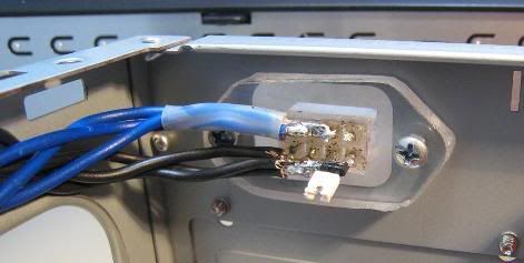
A much better solution would have been to order a Molex 39-01-2081 (8-position panel-mount connector) and eight Molex 44478-3112 crimp-to-wire male contacts from DigiKey.com. Then I would use 18g sheet aluminum instead of the 1/4" acrylic. But I didn't want to wait another three days.
Connecting the PW-200-V to this spiffy new power connector are six 16-gauge wires (3x black for GND, and 3x blue for +12V, because I didn't have any white wire), and made them long enough to route up out of the way. It seemed impossible to solder the six heavy wires directly to the PW-200-V without risk of shorts, so I cut their pair of 18-g wires about 4 cm from the PCB, and spliced my six wires to their two.
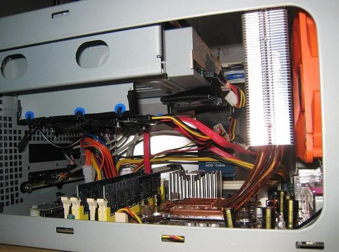
With the stock PSU gone, the interior of the NSK1300 is quite open. Since this build uses a notebook drive and the Conroe isn't too much of a power hog, I hunted for a CPU cooler that could make this work as a single-fan system. I ended up with the Akasa Evo-120.
Several other heatsink options I considered:
#1 Get rid of the optical drive and Antec's slot-in drive-mounting frame with it. Suspend the 2.5" HDD somehow over in the corner above the SATA connectors. Then I'd have bags of room, and could fit a Ninja in there. In fact, I tried this, during some of the testing. But my wife decided she wanted an internal optical drive.
#2 I did some measuring, and I think that if I got a shorter optical drive, a Thermalright HR-01 might just fit. It would be a near thing, and provide zero margin. Its back face would be far enough from the fan as to maybe need a duct (which Thermalright provides).
#3 The Silverstone NT01v2 has an offset/skewed design which would put the HS fin-stack back near the fan, much like what has worked nicely in my NSK2400 box (whose setup I shamelessly copied from Bicster), though rotated by 90 degrees. In the NSK1300, however, there is a lot more vertical space available at the back of the case. So what I really wanted was a taller version of the NT01v2.
#4 Then I discovered the Akasa Evo-120, which looks for all the world like a taller version of the NT01v2. It fits almost perfectly, sitting about 8-11 mm from the exhaust fan, and in pretty good alignment with it, both vertically and side-to-side.
I tried adding a little cardboard ducting to the Evo-120, and it dropped the CPU temps by a degree or so, but I figured the CPU was plenty cool already, and I'd rather have more free airflow to the northbridge, hard drive and memory.
Temperatures: Turns out that the temperature measurements depend a lot) on what BIOS version is flashed into the P5B-VM motherboard. With BIOS version 0405, Speedfan says Sys=45c, CPU=50c, HD0=33c, Core0=46c, Core1=44c, after 20 minutes with 2x CPUBurn. Ambient was about 18c at the time. The Nexus fan is running on 12V.
I considered turning the fan around and going positive pressure. The Evo-120 would be getting ambient temperature air, so the CPU should stay a couple degrees cooler. But, as with the ducting, I figured that the CPU is already cooler than the northbridge and other system components. I decided it's better for the CPU's heat to be immediately removed from the case, rather than blowing that heat inward and trying to cool the NB, RAM, & HDD with pre-heated air. Always tradeoffs.
Other notes...
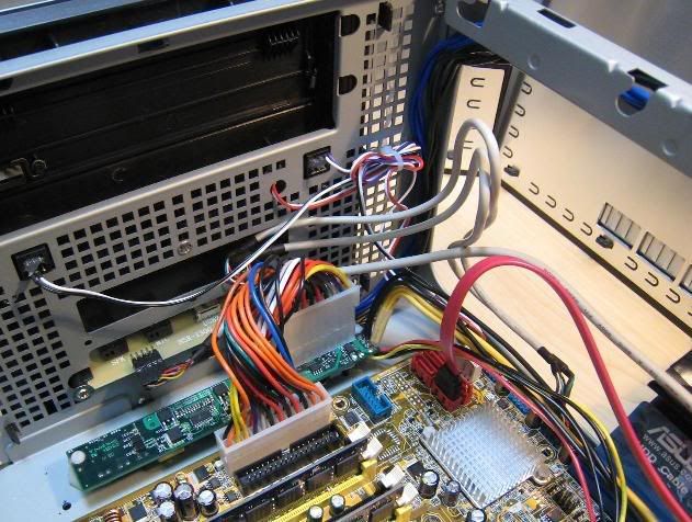
The NSK1300 has the front USB and audio ports on a little beige-colored PCB. With the PW-200-V installed this way, the internal connector for the USB was blocked by the ATX power connecter above the PW-200-V. I bent the 10-pin header for the USB ports from horizontal to vertical. Pry the black plastic spacer off, straighten the pins, push the spacer back on, and clip off the too-tall pins.
I originally tried mounting the PW-200-V the other way round (rotated 180 degrees within the horizontal plane). That way, its 20-pin ATX power connector would be along the edge nearer the mobo, and avoid blocking the front panel audio connector. I later decided I'd rather the input power wires not be any longer than necessary, so I remounted as in the pix. Which is made it necessary to (un)bend the USB connector as just described.
I stated above that the square-ish PW-200-M would not fit in this case, with this mobo. That is not completely true. I measured pretty carefully, and figured that it would fit, but that it would almost exactly butt edge-on against the little PCB the holds the front panel audio and USB connectors. The two PCBs would align vertically, and almost exactly touch, horizontally. If there would be any clearance, it would be less than a millimeter. And the pins of the USB connector (which were projecting horizontally) would poke into the guts of the power circuit. As it turned out, I've had to (un)bend the USB connector anyway. So if I had a do-over, I'd have bought the PW-200-M, and plugged it directly into the motherboard. Unbent both the audio & USB connectors to a vertical orientation. And slipped a piece of thin, heat-resistant dialectric between the two PCBs where they would (nearly) abut.
A word about the Evo-120 v2. I think FrostyTech overstate the differences between the v1 & v2 versions. According to Akasa.co.uk, the heatpipes are 8mm on both. Near as I can tell, a somewhat better-made base is the only difference. But then again, I don't have a v2 for comparison, so I may well be wrong here.
Maybe in future....
Figure out a good way to automatically control the fan speed with temperature. What is now a reasonably quiet PC could idle just a few degrees warmer, and be very quiet.
I considered using a Scythe S-Flex SFF12D (800rpm @ 12V) in place of the Nexus. It's much quieter. But June gets mighty warm in these parts. So I'd rather have the Nexus (or a SFF12E), and somehow control it thermally.
The HDD is sitting directly above the RAM and NB, which I think explains it being a little warm. It might stay cooler if it were somehow suspended vertically, above the southbridge and SATA ports.
Add a low-power 2x DVI video card. It'll be interesting to see the effect on system temps.
I think that an HR-05 (or some such) would fit, on the northbridge. But it would be very near conflicting with the HDD's SATA connector.
Next time I'm ordering something from DigiKey, maybe I'll get one of those 8-pin Molex connectors, and redo my backpanel power connector.
My wife's Linux box needed an upgrade. She's had a Shuttle, and likes the small size, but I (being her system vendor) don't like that Shuttle's chassis are throwaway (i.e. motherboard cannot be replaced). So, with some inspiration from Bluefront, I've tried building a simple system in an Antec NSK1300. I'm less skilled/patient/industrious than Bluefront, whose case is an Antec Aria, kind of like Mark Martin's car is a Chevy Monte Carlo. So I tried to get 75% of the benefit with 15% of the effort. The rough plan was to discard the stock PSU from the NSK1300, put a 120mm fan in its place, and power the system using an external power-brick and an efficient DC-DC converter. In case any of this is helpful to anyone who might be itching to build a reasonably quiet SFF desktop, here's what I did...
Cast of Characters:
Mobo : ASUS P5B-VM
CPU : C2D E6300 (I should have opted for the E6600)
HDD : Hitachi 7K100 (2.5" 7200rpm)
CDRW : some old Lite-On
Case : Antec NSK1300 with stock PSU removed
CPU HS : Akasa Evo-120 (AK-920)
AC/DC : Dell 220W external brick power adapter ($40 via eBay)
DC/DC : Mini-Box PW-200-V DC/DC converter
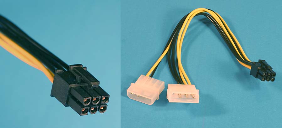
Right now the onboard VGA drives a 1600x1200 CRT, but at some point we'll add a low-power 2x DVI graphics card, to run a pair of 1600x1200 LCDs (her work is all 2-D, but lots of pixels is nice). So I wanted more power headroom than I'd have from a 120W picoPSU. Mini-Box offer their 200W DC/DC design on either a square-ish PCB (PW-200-M) or a long skinny PCB (PW-200-V). Plugged directly into the ATX power connector on the P5B-VM, neither of these would fit in the case. (This is not strictly true, as I'll confess later). Bluefront has a shorter than normal mATX motherboard in his Aria, which is why he has plenty of room for his PW-200-M. So I mounted the PW-200-V upside-down in front of the mobo, and used a generic 20pin-24pin ATX adapter cable to connect it.
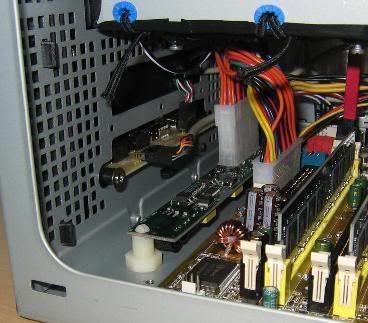
To mount the DC/DC, I found 3/8 x 2 inch hex-head nylon cap screws at a hardware store. Cut off the end, drilled and 6-32 tapped through the axis, and filed the shoulder of one of them to provide clearance for a capacitor at the end of the PW-200-V. I drilled a couple of holes in the floor of the case, and used 6-32 x 3/8 machine screws to fasten the nylon pillars to the base. The pillars provide a sturdy mounting, and are non-conductive -- the PW-200-V's mounting holes are perilously near to exposed 12V wires.
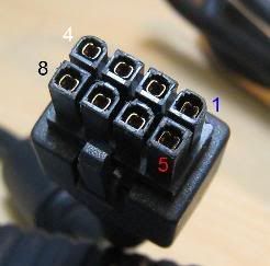
Various threads (e.g. 28246,29018) have discussed modding the Dell 150W or 220W AC/DC adapters for use with DC/DC desktops. I'd rather not burn my house down, so I opened my brick and traced out enough of the DC end of the circuit to convince myself that the adapter does work as simply as the various forum posts suggest. Dell has multiple sources for these 220W bricks. Most people mention Delta. Mine happens to be made by HiPro (ZVC220HD12S1). The Dell end of it should be the same, regardless of the manufacturer. The cable is 8 conductor, though pin 1 is unused.
The pinout, numbered as in the picture, is:
1: N/C. Soldered to a through-hole in the adapter's PCB, but that through-hole is not connected to anything else on the PCB.
2,3,4 : +12V. Three white wires to carry the outbound current. Two meters of 16 gauge copper is about 24 mOhm, and 18 Amps through that would be about a 425 mV drop, so this adapter triples the wire, dividing the drop by three (i.e. 142 mV at max current). The three wires solder together into one big hole in the adapter's PCB.
Pin 5 : 'Trigger.' There's a pullup resistor in the brick which causes this signal to float up to a few volts. Short this line to ground, and the adapter goes from Standby (amber LED) to On (green LED).
Pins 6,7,8 : Ground. Three black 16g wires. They have to carry all that 18 A current back to the adapter, so unfortunately, this means that 'ground' inside this PC is up to 142 mV higher potential than earth. All three are soldered together into one hole in the adapter's PCB ground plane.
Aside: The adapter's PCB ground plane is then directly connected to the earth pin of the AC mains connector. Thus the 142 mV 'ground' on my mobo could create issues if I had an external (e.g. USB) peripheral that powered by a power adapter with three-wire mains that was similarly connected. I could wind up dumping quite a lot of current through the shield on a USB cable. Perhaps I shouldn't be surprised to see this, in cost-sensitive consumer commodity designs (i.e. a Dell laptop), but it's something to keep in mind when using this type of setup.
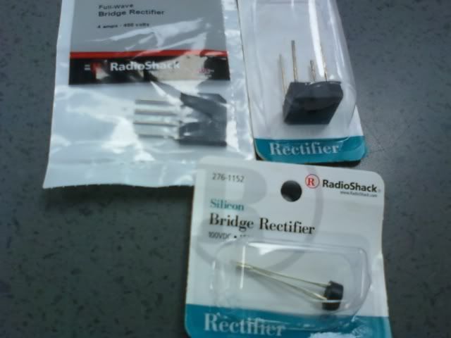
The PW-200-V came with 12 inch power input leads (18 gauge wire!) terminated with a 5mm barrel connector socket. Most users who've posted on these forums have gone to Radio Shack etc and found a plug to fit it. However, barrel connectors like this are generally rated for less than one amp. I opted to keep the Dell power-brick and it's connector intact, and find a mating connector. I desoldered the 24-pin ATX power socket from an old ATX motherboard. I cut it in two (leaving only positions 1-4 & 13-16), to make myself an 8-pin connector which mates perfectly with the connector on the Dell brick. These Molex connectors are rated for 6 A per pin.
To mount this spiffy new power connector into the back panel, I cut a small piece of 1/4 inch acrylic, drilled two mounting holes, and cut a rectangular hole in the center into which my new 8-pin connector press-fit. A drop of superglue secured the connector into the acrylic. The three +12V and three GND wires are soldered across the two threesomes of pins (I'd recommend a more powerful soldering iron than the 25W cheapo I used for this - three 16g wires sink a lot of heat, so my soldering is marginal). I added a two-pin header, from the trigger to GND, and a jumper across it, to enable or standby the powerbrick. Not really necessary - I could have just soldered from GND to Trigger.
A much better solution would have been to order a Molex 39-01-2081 (8-position panel-mount connector) and eight Molex 44478-3112 crimp-to-wire male contacts from DigiKey.com. Then I would use 18g sheet aluminum instead of the 1/4" acrylic. But I didn't want to wait another three days.
Connecting the PW-200-V to this spiffy new power connector are six 16-gauge wires (3x black for GND, and 3x blue for +12V, because I didn't have any white wire), and made them long enough to route up out of the way. It seemed impossible to solder the six heavy wires directly to the PW-200-V without risk of shorts, so I cut their pair of 18-g wires about 4 cm from the PCB, and spliced my six wires to their two.
With the stock PSU gone, the interior of the NSK1300 is quite open. Since this build uses a notebook drive and the Conroe isn't too much of a power hog, I hunted for a CPU cooler that could make this work as a single-fan system. I ended up with the Akasa Evo-120.
Several other heatsink options I considered:
#1 Get rid of the optical drive and Antec's slot-in drive-mounting frame with it. Suspend the 2.5" HDD somehow over in the corner above the SATA connectors. Then I'd have bags of room, and could fit a Ninja in there. In fact, I tried this, during some of the testing. But my wife decided she wanted an internal optical drive.
#2 I did some measuring, and I think that if I got a shorter optical drive, a Thermalright HR-01 might just fit. It would be a near thing, and provide zero margin. Its back face would be far enough from the fan as to maybe need a duct (which Thermalright provides).
#3 The Silverstone NT01v2 has an offset/skewed design which would put the HS fin-stack back near the fan, much like what has worked nicely in my NSK2400 box (whose setup I shamelessly copied from Bicster), though rotated by 90 degrees. In the NSK1300, however, there is a lot more vertical space available at the back of the case. So what I really wanted was a taller version of the NT01v2.
#4 Then I discovered the Akasa Evo-120, which looks for all the world like a taller version of the NT01v2. It fits almost perfectly, sitting about 8-11 mm from the exhaust fan, and in pretty good alignment with it, both vertically and side-to-side.
I tried adding a little cardboard ducting to the Evo-120, and it dropped the CPU temps by a degree or so, but I figured the CPU was plenty cool already, and I'd rather have more free airflow to the northbridge, hard drive and memory.
Temperatures: Turns out that the temperature measurements depend a lot) on what BIOS version is flashed into the P5B-VM motherboard. With BIOS version 0405, Speedfan says Sys=45c, CPU=50c, HD0=33c, Core0=46c, Core1=44c, after 20 minutes with 2x CPUBurn. Ambient was about 18c at the time. The Nexus fan is running on 12V.
I considered turning the fan around and going positive pressure. The Evo-120 would be getting ambient temperature air, so the CPU should stay a couple degrees cooler. But, as with the ducting, I figured that the CPU is already cooler than the northbridge and other system components. I decided it's better for the CPU's heat to be immediately removed from the case, rather than blowing that heat inward and trying to cool the NB, RAM, & HDD with pre-heated air. Always tradeoffs.
Other notes...
The NSK1300 has the front USB and audio ports on a little beige-colored PCB. With the PW-200-V installed this way, the internal connector for the USB was blocked by the ATX power connecter above the PW-200-V. I bent the 10-pin header for the USB ports from horizontal to vertical. Pry the black plastic spacer off, straighten the pins, push the spacer back on, and clip off the too-tall pins.
I originally tried mounting the PW-200-V the other way round (rotated 180 degrees within the horizontal plane). That way, its 20-pin ATX power connector would be along the edge nearer the mobo, and avoid blocking the front panel audio connector. I later decided I'd rather the input power wires not be any longer than necessary, so I remounted as in the pix. Which is made it necessary to (un)bend the USB connector as just described.
I stated above that the square-ish PW-200-M would not fit in this case, with this mobo. That is not completely true. I measured pretty carefully, and figured that it would fit, but that it would almost exactly butt edge-on against the little PCB the holds the front panel audio and USB connectors. The two PCBs would align vertically, and almost exactly touch, horizontally. If there would be any clearance, it would be less than a millimeter. And the pins of the USB connector (which were projecting horizontally) would poke into the guts of the power circuit. As it turned out, I've had to (un)bend the USB connector anyway. So if I had a do-over, I'd have bought the PW-200-M, and plugged it directly into the motherboard. Unbent both the audio & USB connectors to a vertical orientation. And slipped a piece of thin, heat-resistant dialectric between the two PCBs where they would (nearly) abut.
A word about the Evo-120 v2. I think FrostyTech overstate the differences between the v1 & v2 versions. According to Akasa.co.uk, the heatpipes are 8mm on both. Near as I can tell, a somewhat better-made base is the only difference. But then again, I don't have a v2 for comparison, so I may well be wrong here.
Maybe in future....
Figure out a good way to automatically control the fan speed with temperature. What is now a reasonably quiet PC could idle just a few degrees warmer, and be very quiet.
I considered using a Scythe S-Flex SFF12D (800rpm @ 12V) in place of the Nexus. It's much quieter. But June gets mighty warm in these parts. So I'd rather have the Nexus (or a SFF12E), and somehow control it thermally.
The HDD is sitting directly above the RAM and NB, which I think explains it being a little warm. It might stay cooler if it were somehow suspended vertically, above the southbridge and SATA ports.
Add a low-power 2x DVI video card. It'll be interesting to see the effect on system temps.
I think that an HR-05 (or some such) would fit, on the northbridge. But it would be very near conflicting with the HDD's SATA connector.
Next time I'm ordering something from DigiKey, maybe I'll get one of those 8-pin Molex connectors, and redo my backpanel power connector.