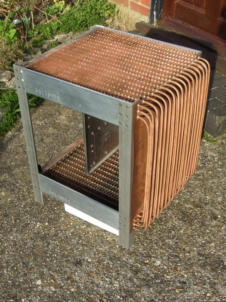
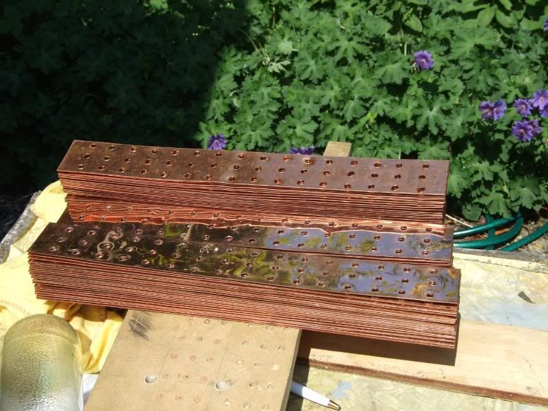
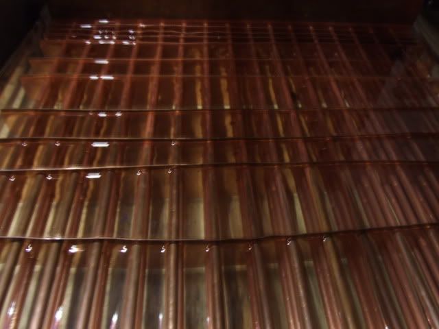
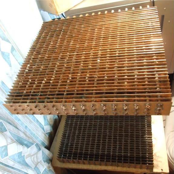
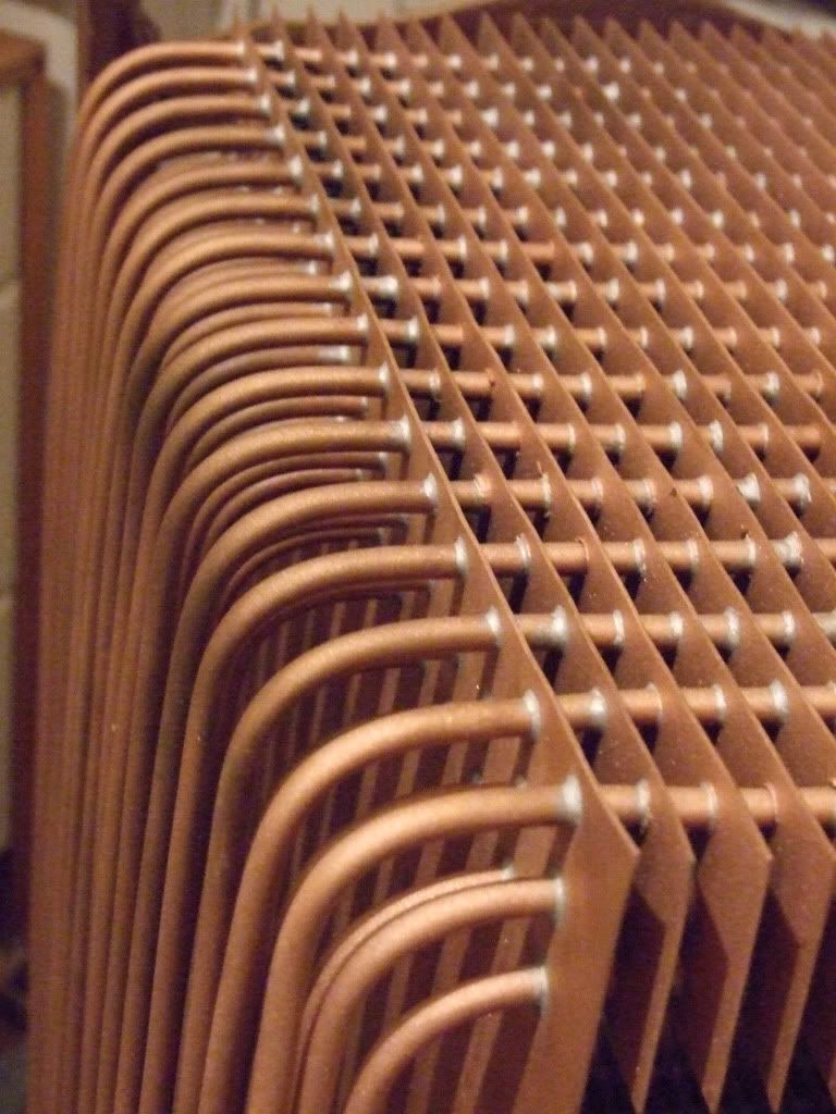
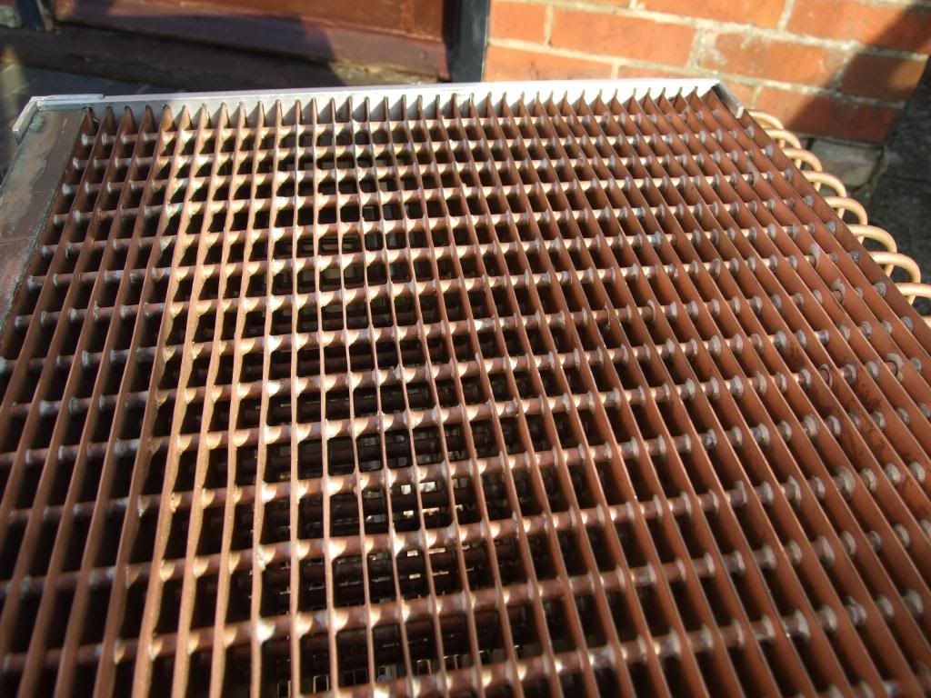
I then needed to drill 48 x 6mm holes in each of the copper fins and the copper wall.

This took
a while.
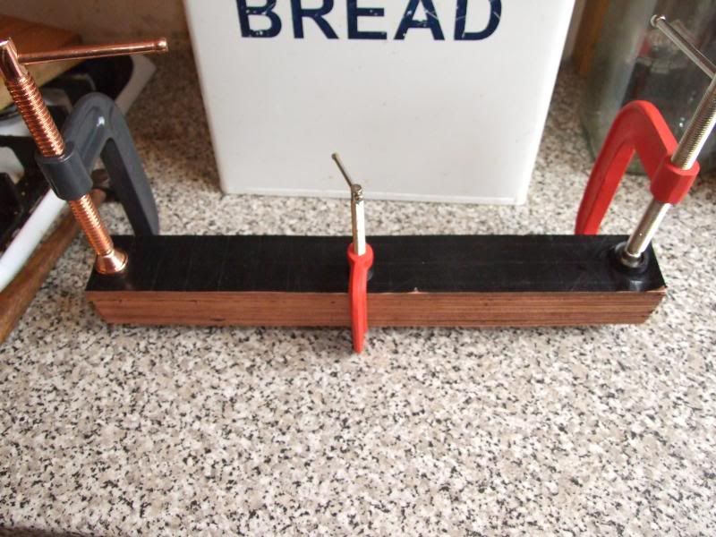
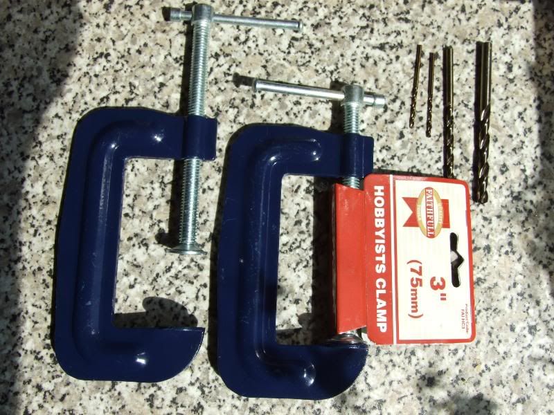
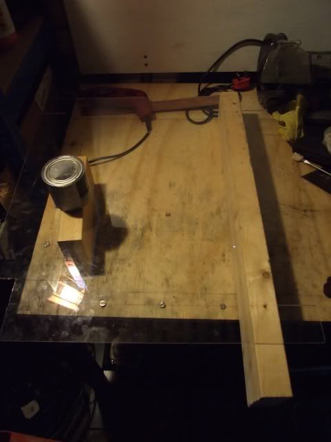
I initially tried using G-clamps and my bench drill and ran into several problems. As the holes were drilled, they pushed a cusp through, deforming the clamped stack. Whilst the cusp/sleeve from drilling is actually useful for soldering and heat transfer, it introduces inaccuracy in the drilling. So I made a jig for putting the copper strips in for drilling.
JIG FOR DRILLING
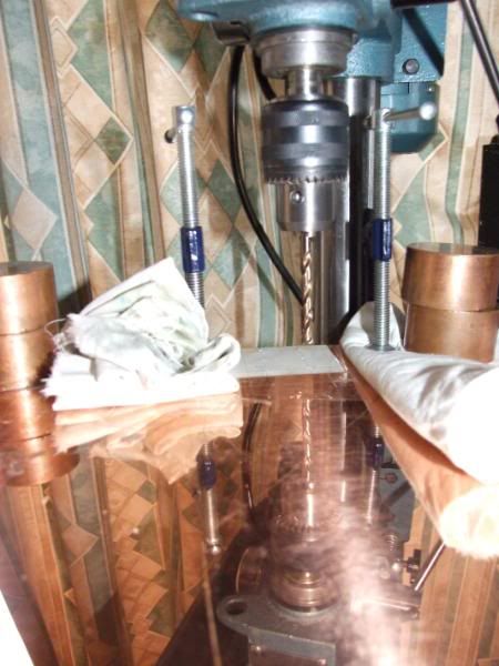
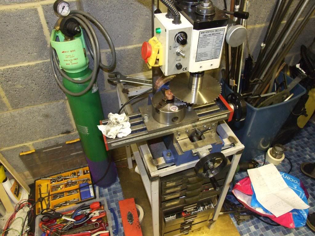
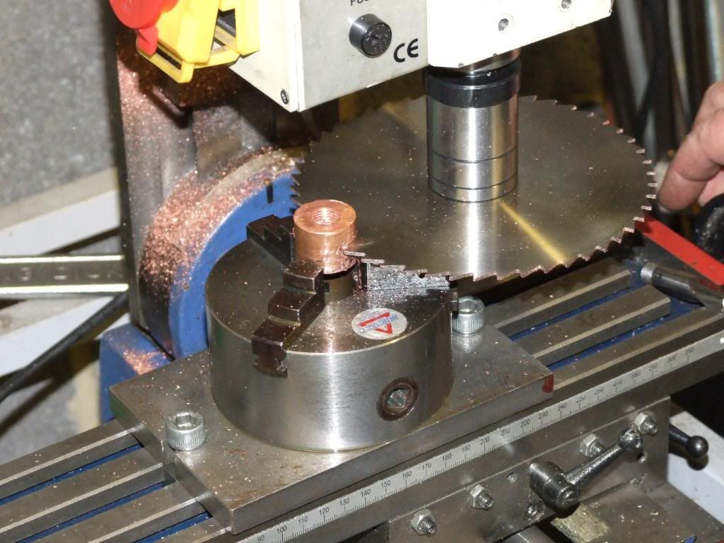
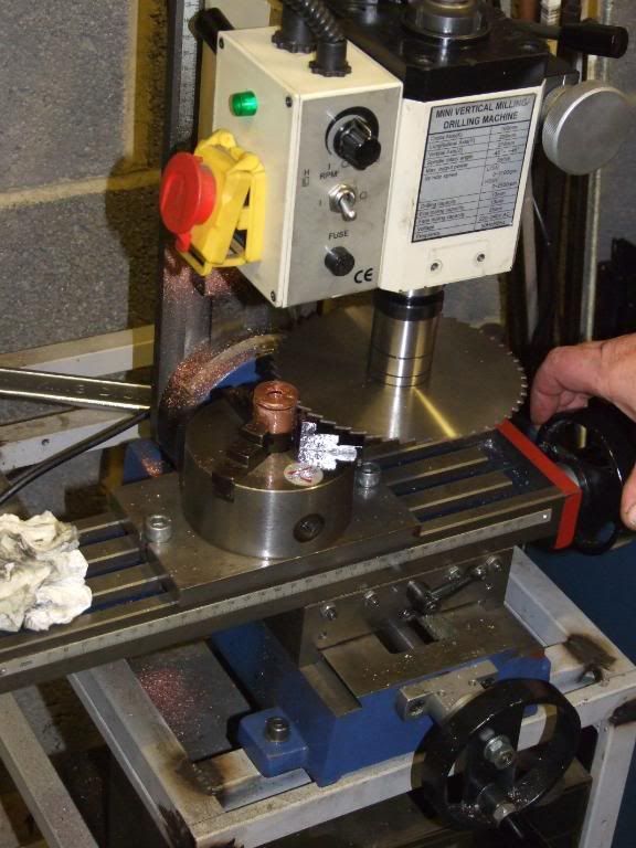
Sadly the bench drill I have is only 180W, and so lacks the torque to drill large metal holes, so I switched to using an 810W hand drill in a heavy duty drill stand, which allows accurate vertical drilling.
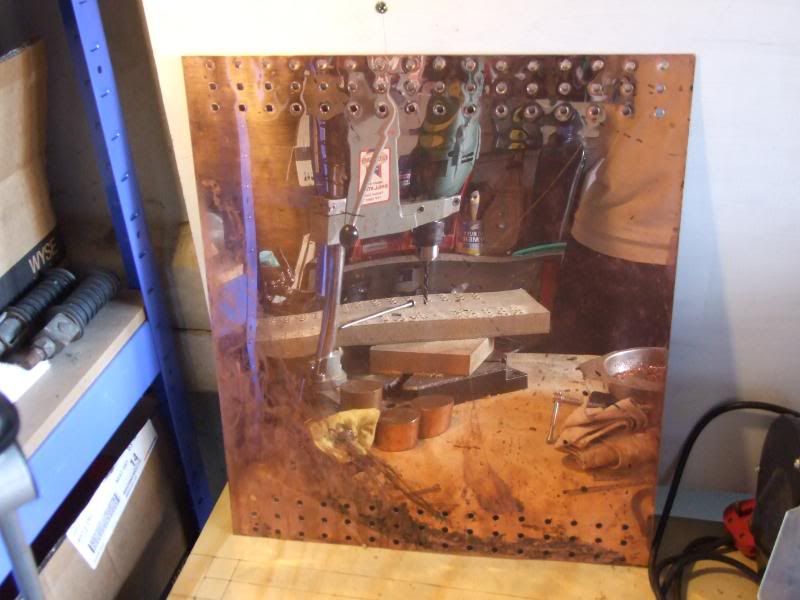
PICS OF DRILLING
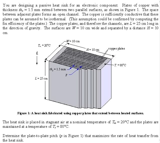
After doing some reading up on natural convection and passive heatsink design, I came across a problem sheet set for engineering students on how to optimise the fin spacing for a passive radiator, from a book by a couple of heat transfer professors, and even better, the software it ran on was freely available on the web.

So, using the software, I adjusted the parameters to model my heatsink as best I could.
Passive heatsinks rely on natural convection, and this requires the free movement of air over the fins. The fins are much more effective spaced much further apart than in air-cooled heatsinks (~2mm for a Thermalright Ultra Extreme) or even the most sparsely-finned watercooling radiators (~1fin/3.125mm or 8fpi for an RX XSPC radiator).
The simulator models a given width, height and depth of passive heatsink at a given input heatload, and plots the heat transfer of a given fin, and the total heat transfer of all fins combined, at varying fins spacings.
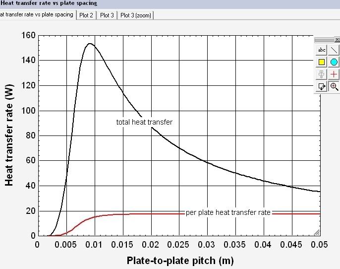
So, whilst the heat transfer for a single fin increases up to a certain point, increased fin spacing means fewer heatfins overall. There's a balance between the two, giving an optimal spacing for a given heatload:
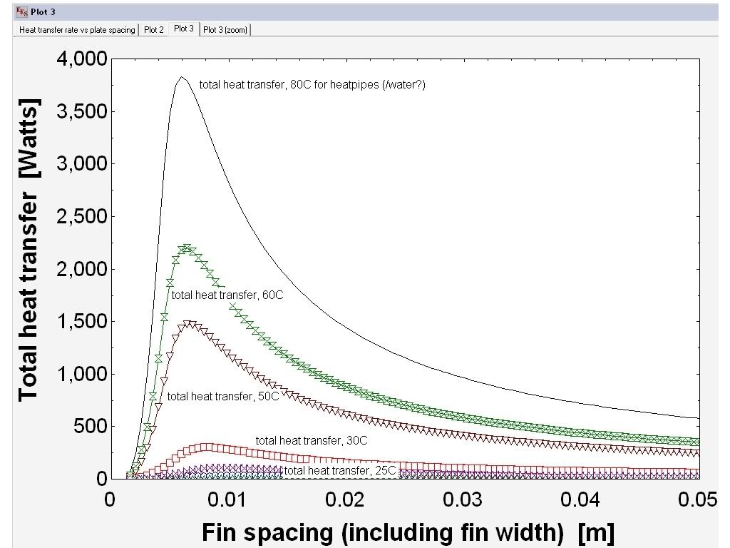
From the simulator there's also another interesting trend - as the input heatload decreases, the optimal fin spacing (fin-pitch) increases, which means I need to optimise the heatfin spacing for the air-water delta T I want to aim for...
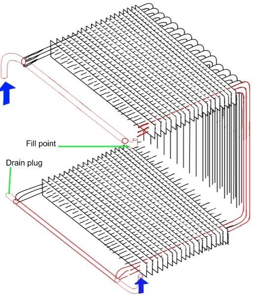
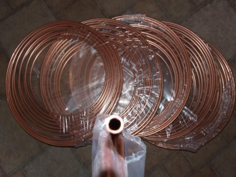
The simulator mathematically models a heatsink made from two copper plates held at a set temperature with heatfins that run perpendicular between them, so it's not exactly what my heatsink design is, and in adapting it to model my design I'm not entirely sure how to adapt mine to it, since my design has 48 6mm outer diameter, 4.8mm inner diameter tubes running through the heatfins. I'm unsure as to whether I should adapt it so I equalise the inner heatpipe surface area (4.8mm)to the end-heatplate- to-heatfin surface area in the model, or the outer heatpipe (6mm) surface area... Hope that makes sense!
I altered the parameters to assume just two end heatplates as in the original design, to give a conservative estimate of the performance, and the heatfin spacing (1 heatfin per 10mm, so about 9.1mm between each heatfin). This gave around a 300w heat transfer for a delta of 10C between the air (20C) and the heatpipe/water temperature (30C). But as I say, this is hopefully the worst-case scenario (though the model uses copper-copper joins rather than soldered joints...). A point to note is that the model only calculates the heat transfer from the heatfins - it excludes the heat transfer from the copper tube surface area (~11,000cm^2) and the copper wall (~3,600cm^2).
PIC WORSTCASE SCENARIO (spacing of 10mm on the x-axis)
Adjusting the model to equalise the end plate-to-heatfin surface area in the model with the tube-to-heatfin surcace area gives silly numbers (~560W heat transfer at a 0.5C Delta T, 400W for a 0.4C Delta T).
The real performance will probably lie somewhere inbetween - whilst the best case scenario is probably largely correct in terms of more accurate surface area for the water to transfer heat to the pipes and fins, the model assumes continuous copper joints, and inaccuracies in hole size and loss from soldered joints (~96% tin/ 3.5%Silver/0.5% copper solder) will no doubt lower performance.
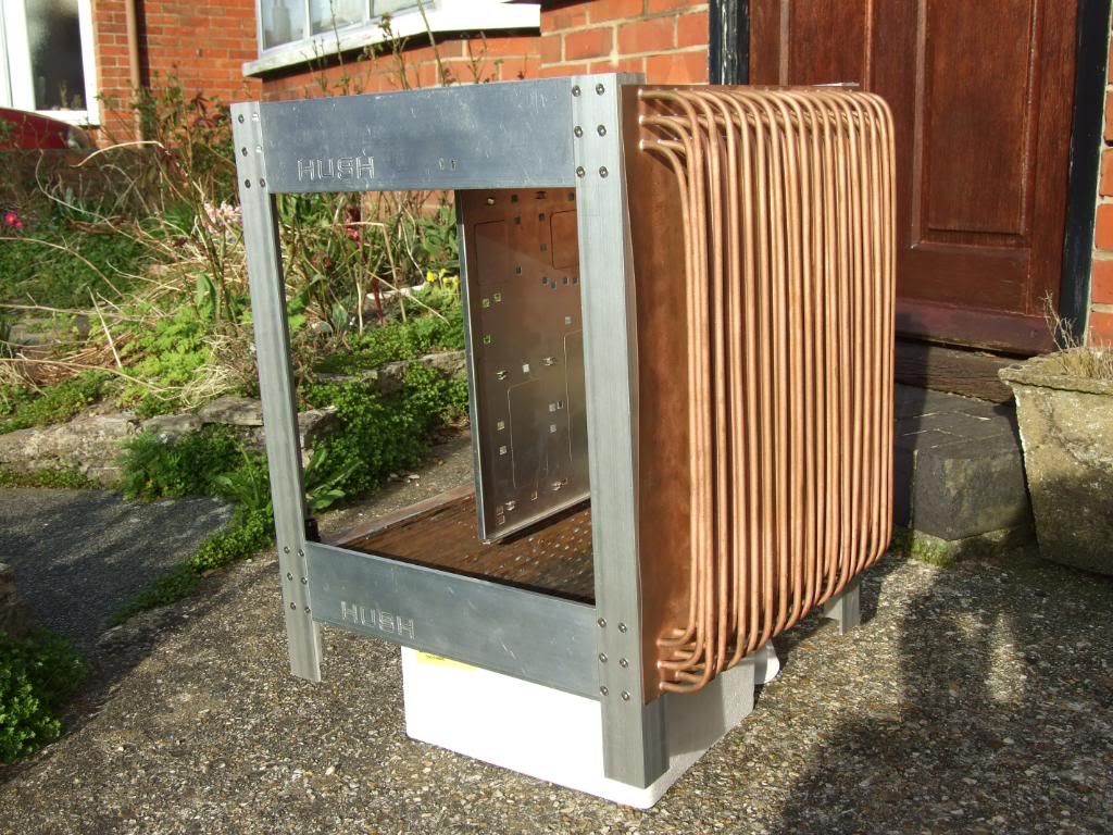
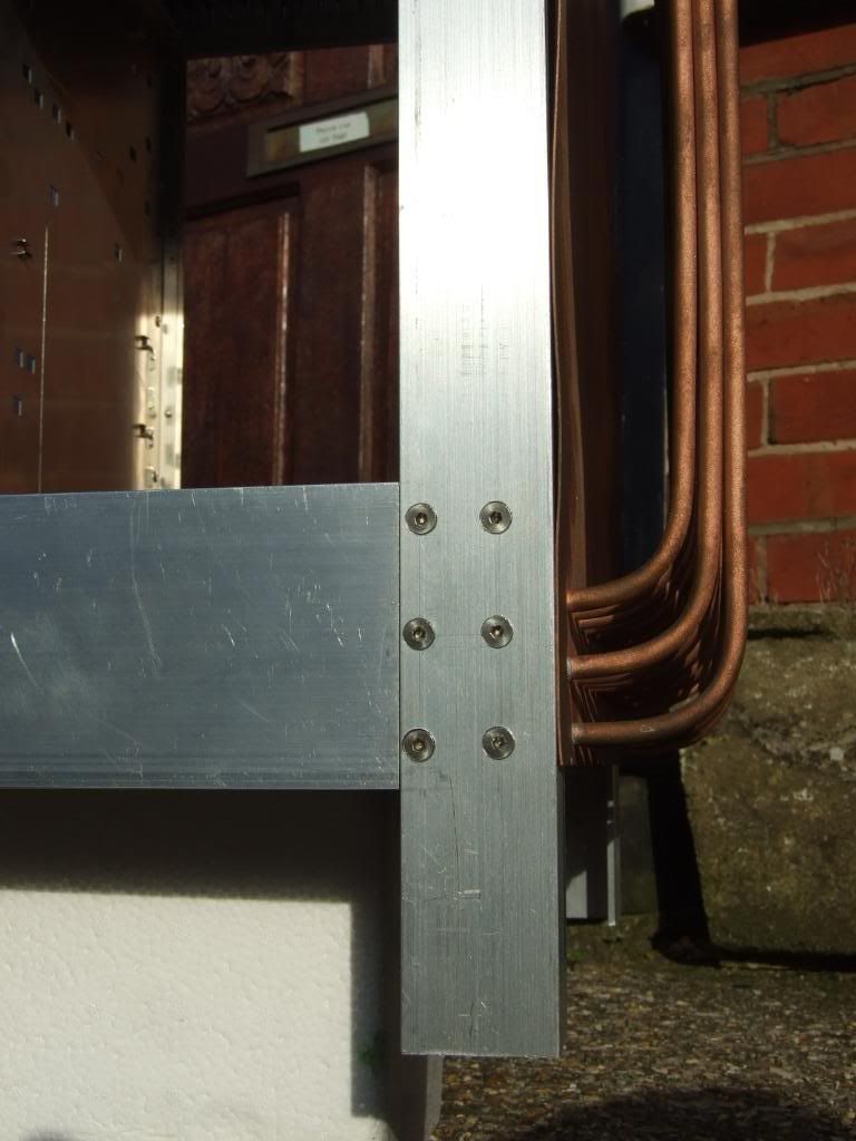
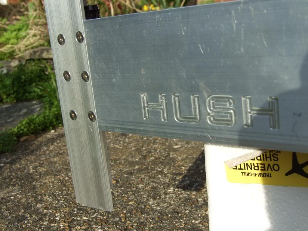
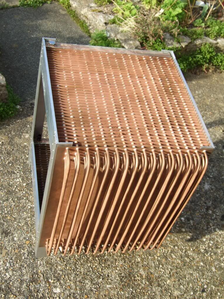
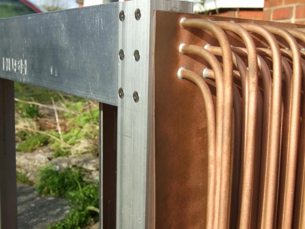
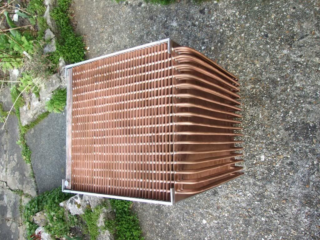
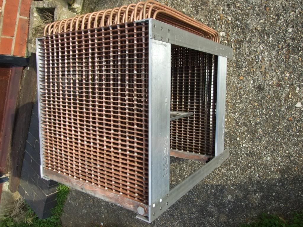
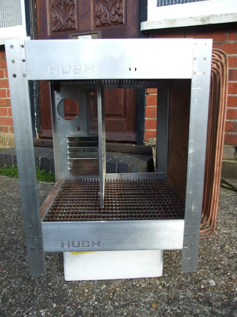
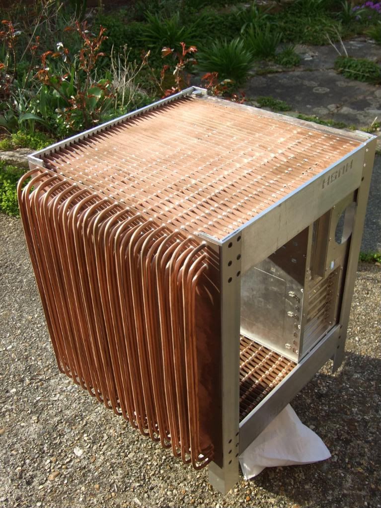
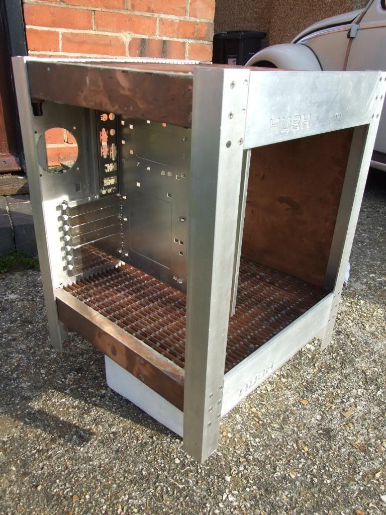
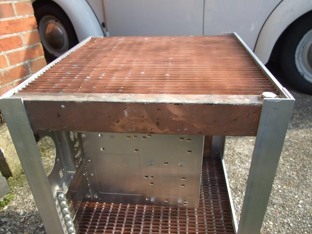
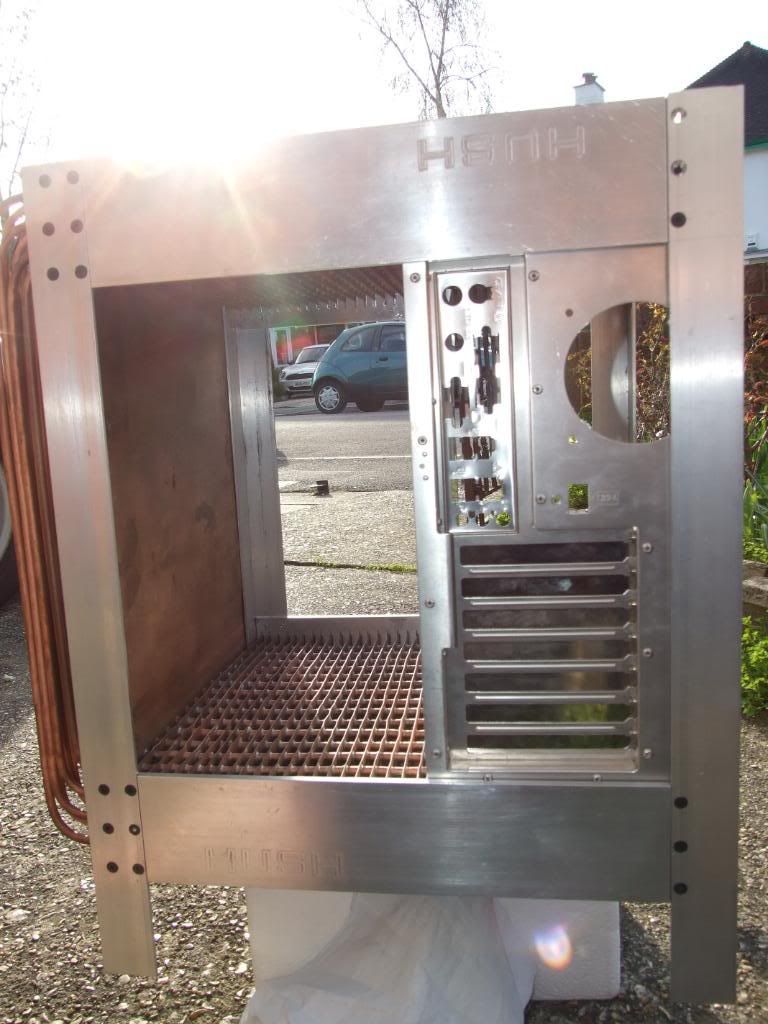
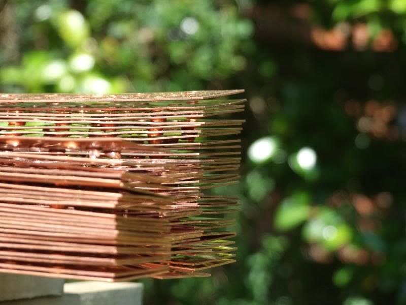
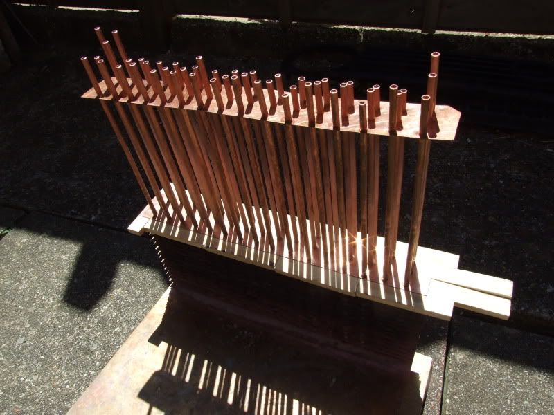
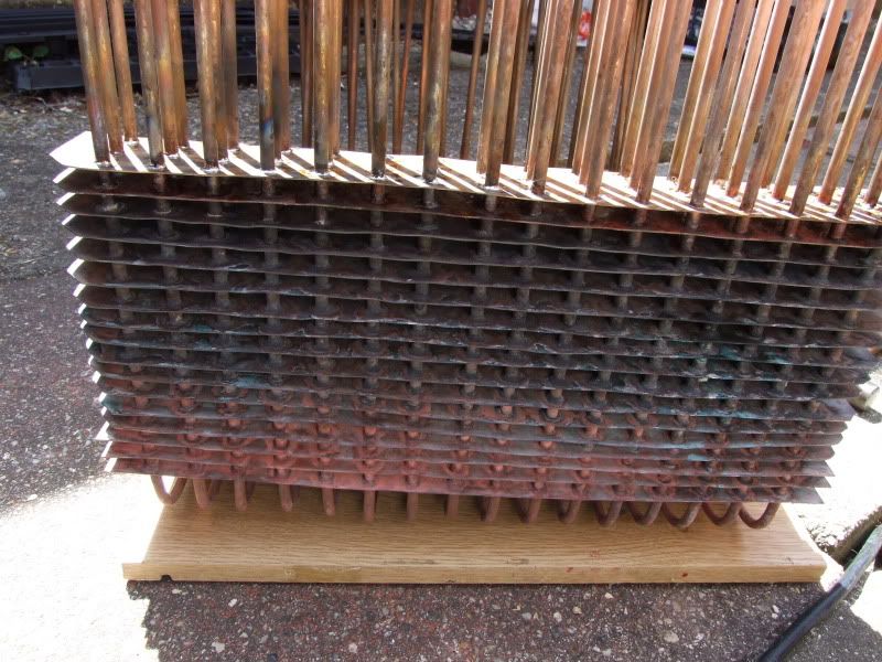
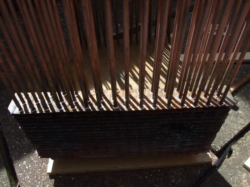
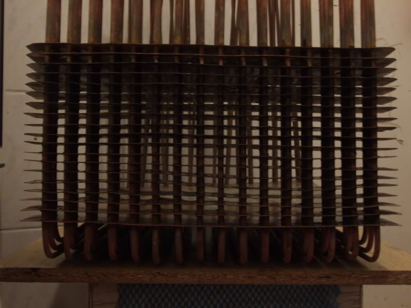
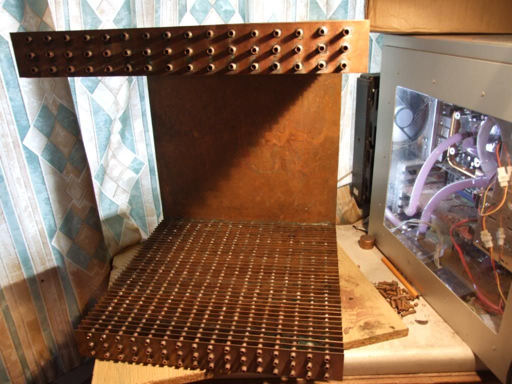
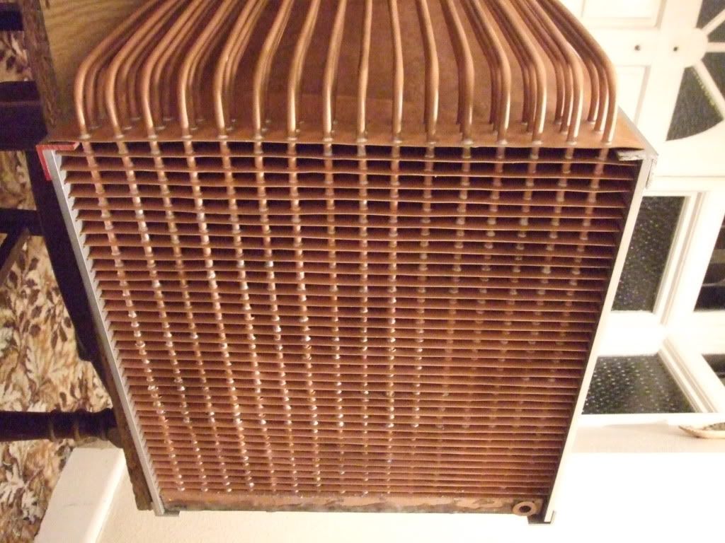
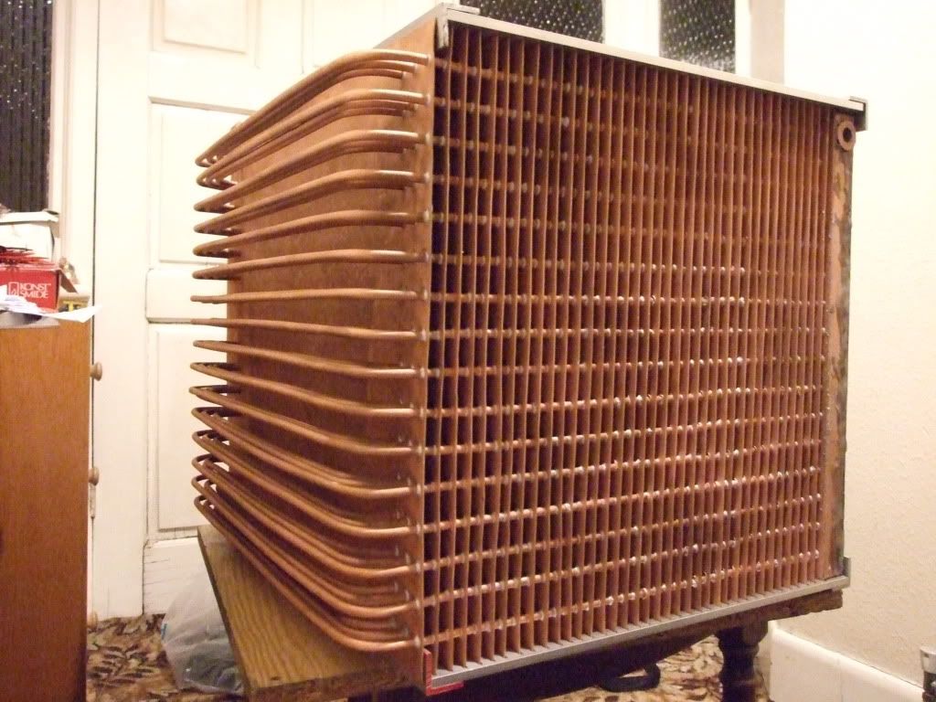
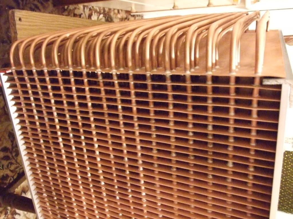
Anyhow, enough hypotheticals, here are some pics of where the project is up to at the moment.
After drilling the heatfins I found the holes were marginally too small, using a digital Vernier, in th order of a few hundredths of a mm.
PIC OF DIGITAL VERNIER
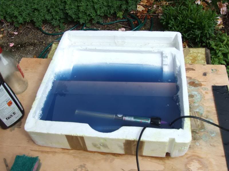
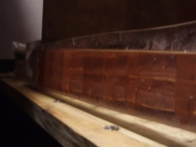
So I decided to erode them down slightly by putting them in a drainpipe full of vinegar and harpic toilet cleaner (since it's hydrochloric acid based). I must say, looking through household detergent ingredients for the strongest acid in the supermarket made me feel like a terrorist!
PIC OF TUBES IN DRAINPIPE
PIC OF TUBES OUT OF DRAINPIPE
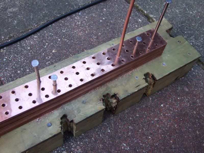
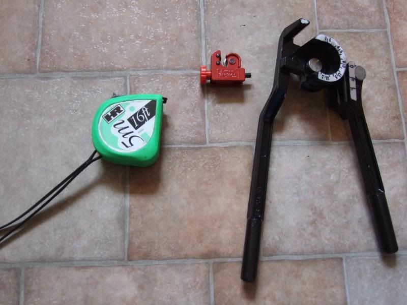
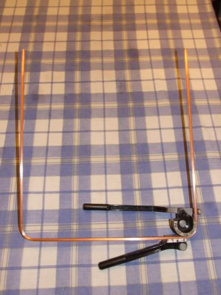
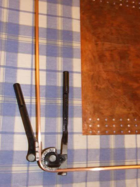
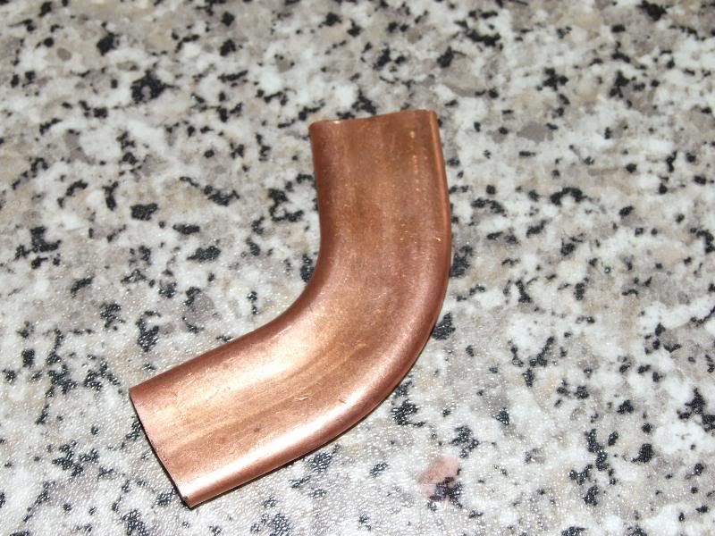
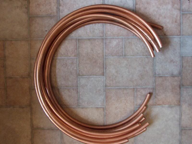
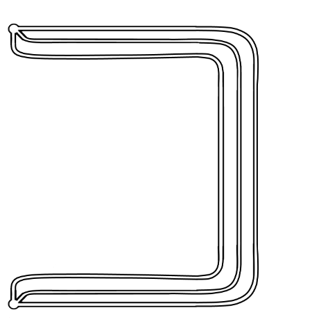
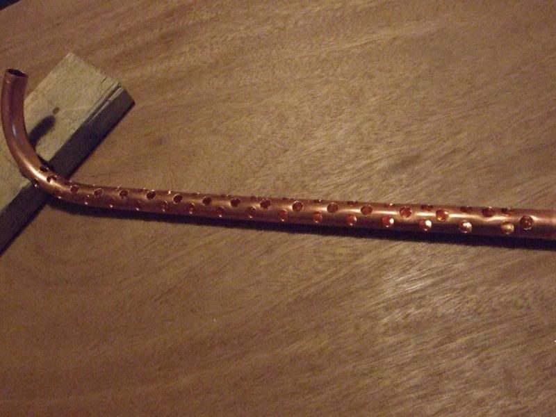
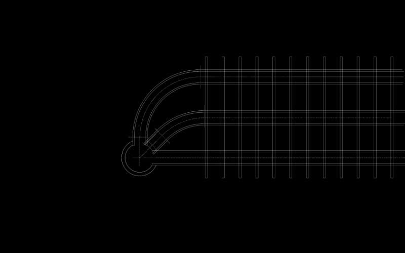
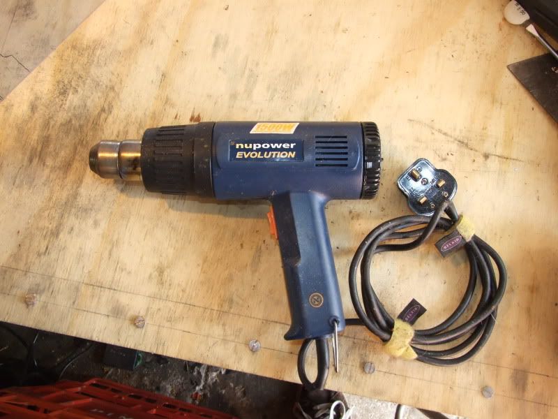
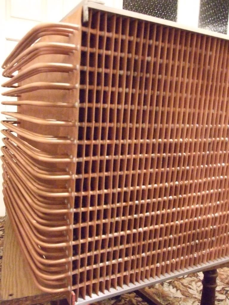
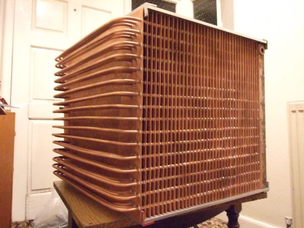
I then used a microbore pipe bender to make the bends in the pipe. It's a handy little tool, but unfortunately they put far too much paint on it, meaning the measuring bits and the 6mm tube channel was too small, meaning the tube wouldn't get equal pressure around it when bending and would deform too much for my liking. After a quick bit of paintstripping with Nitromors I bent the tubes for insertion into the copper wall. This was a bit fiddly; in order for the bends to line up exactly with the drilled holes I needed to know amount of length the bend took. After a few annoying mishaps, annealing and restraightening I got the tubes bent accurately.

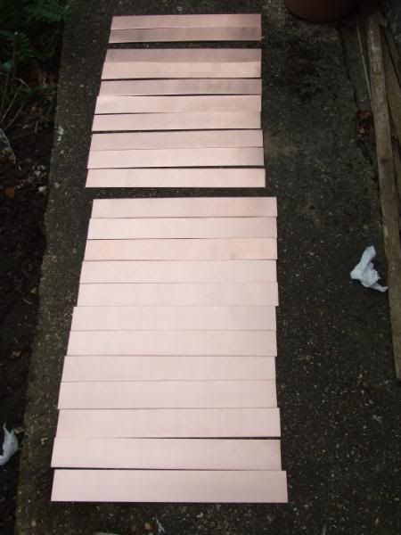
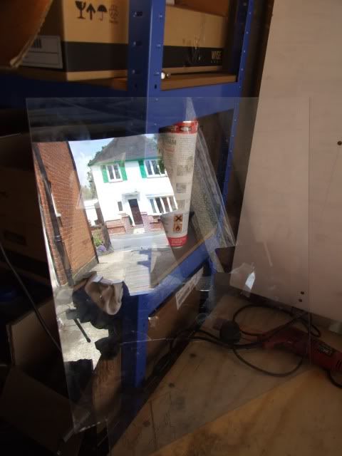
 , and for a small extra charge the seller was even willing to cut it with a metal shear into lots of 395mm x 50mm strips for the heatfins. So the dimensions of the whole thing changed, and the drilled pipes were now the wrong size. Ho hum.
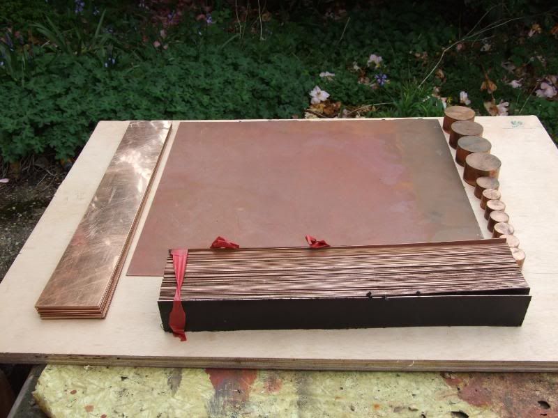
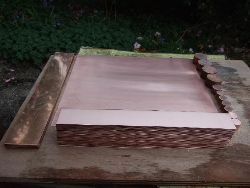
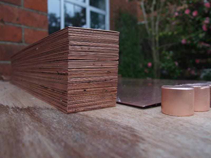
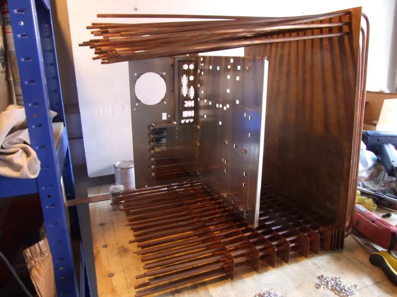
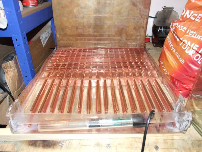
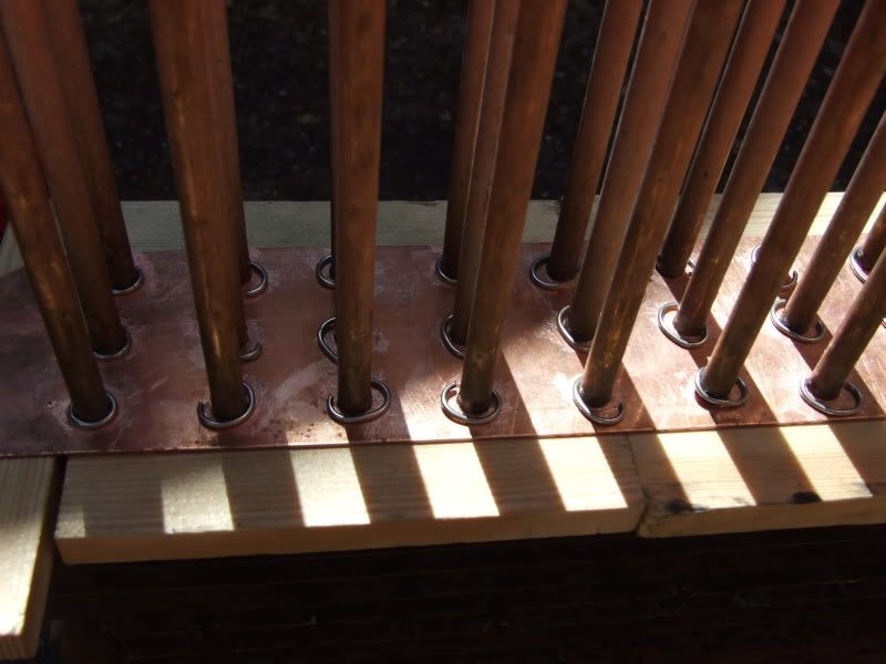
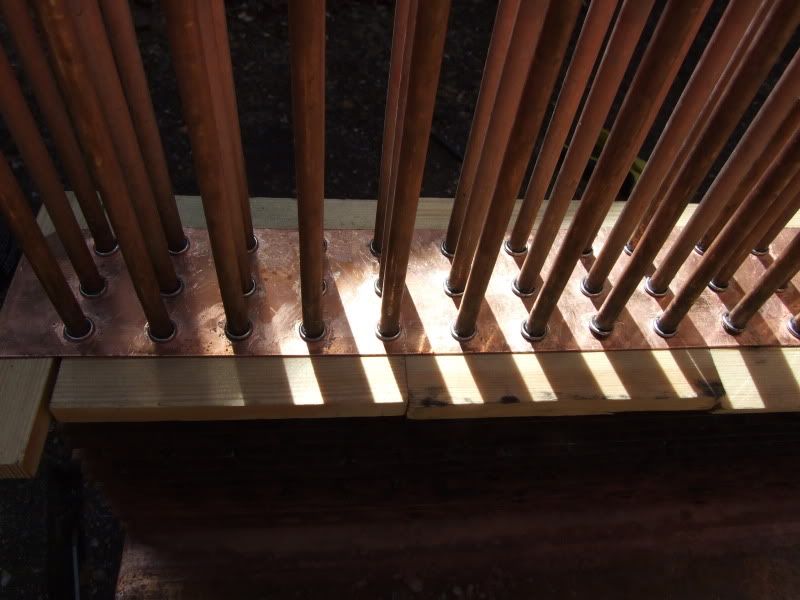
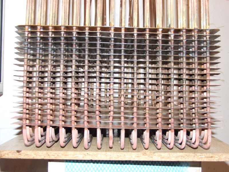
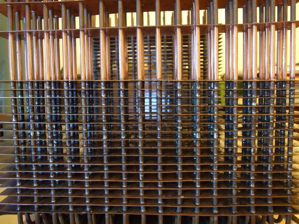
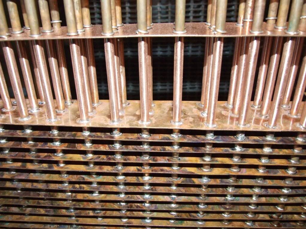
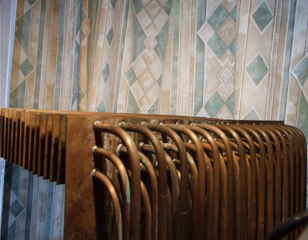
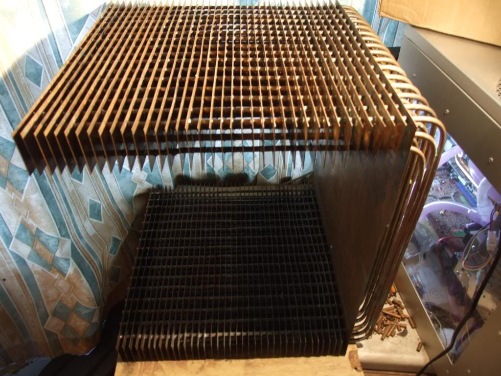
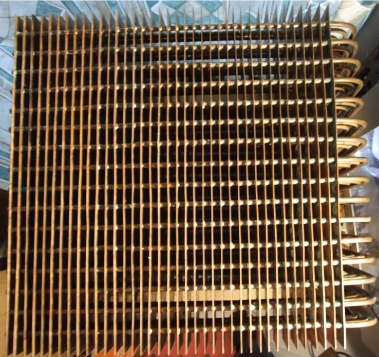
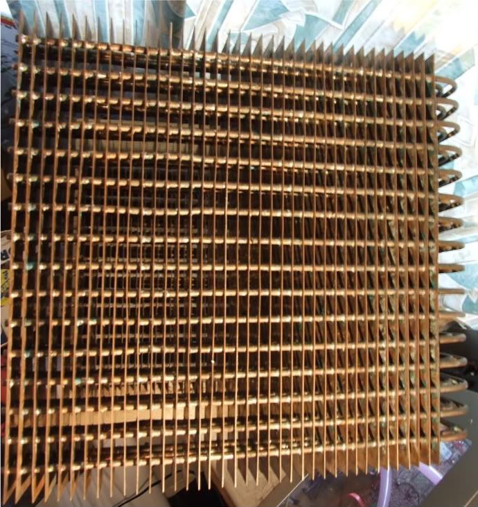
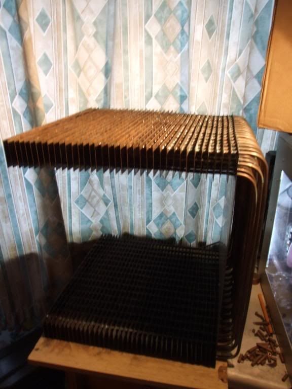
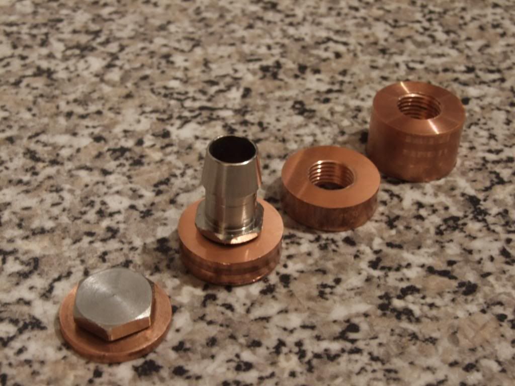
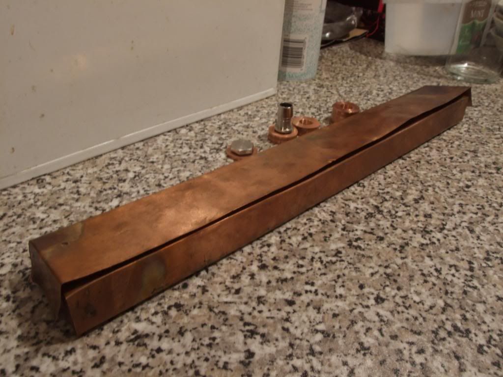
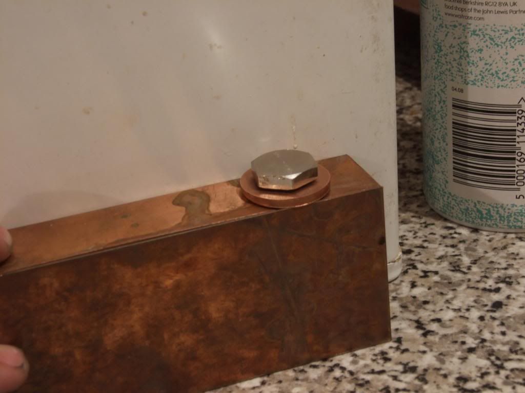
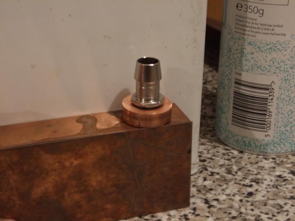
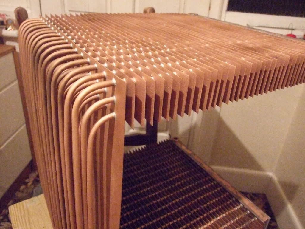
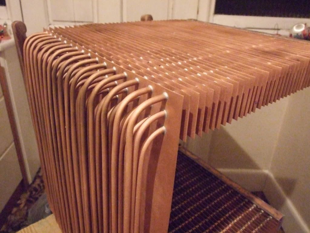
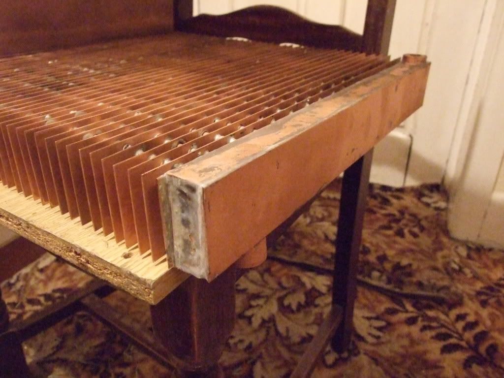
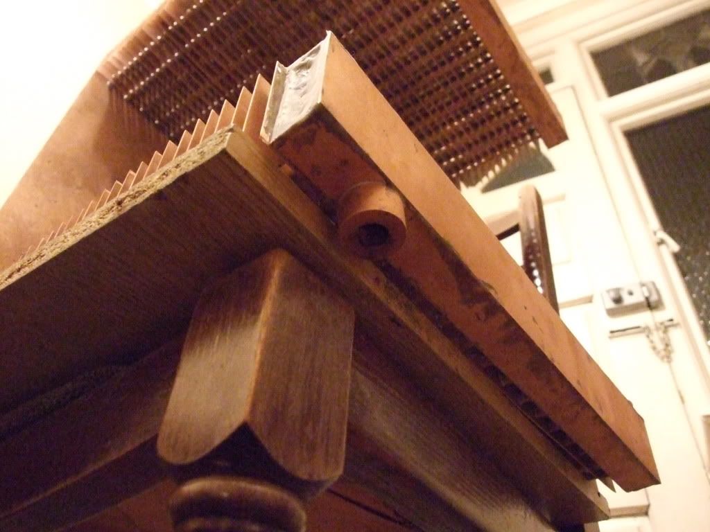
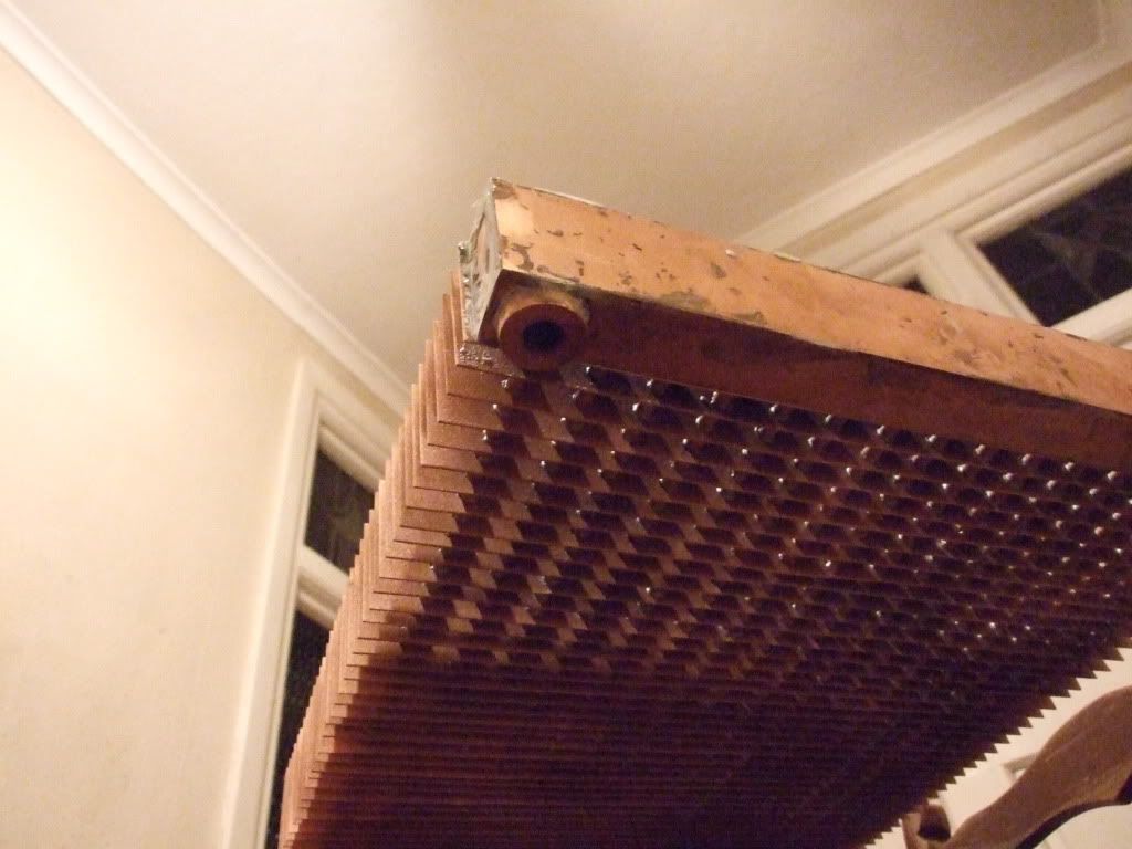
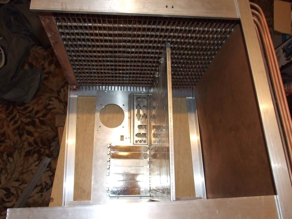
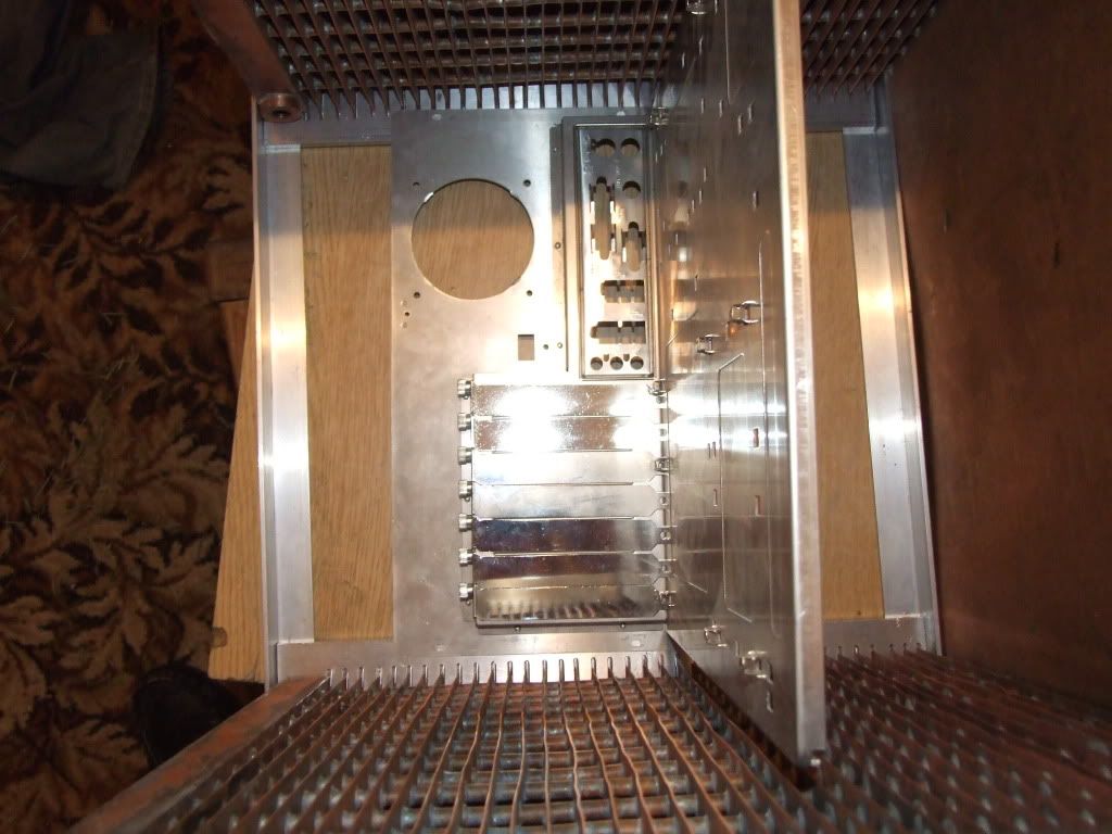
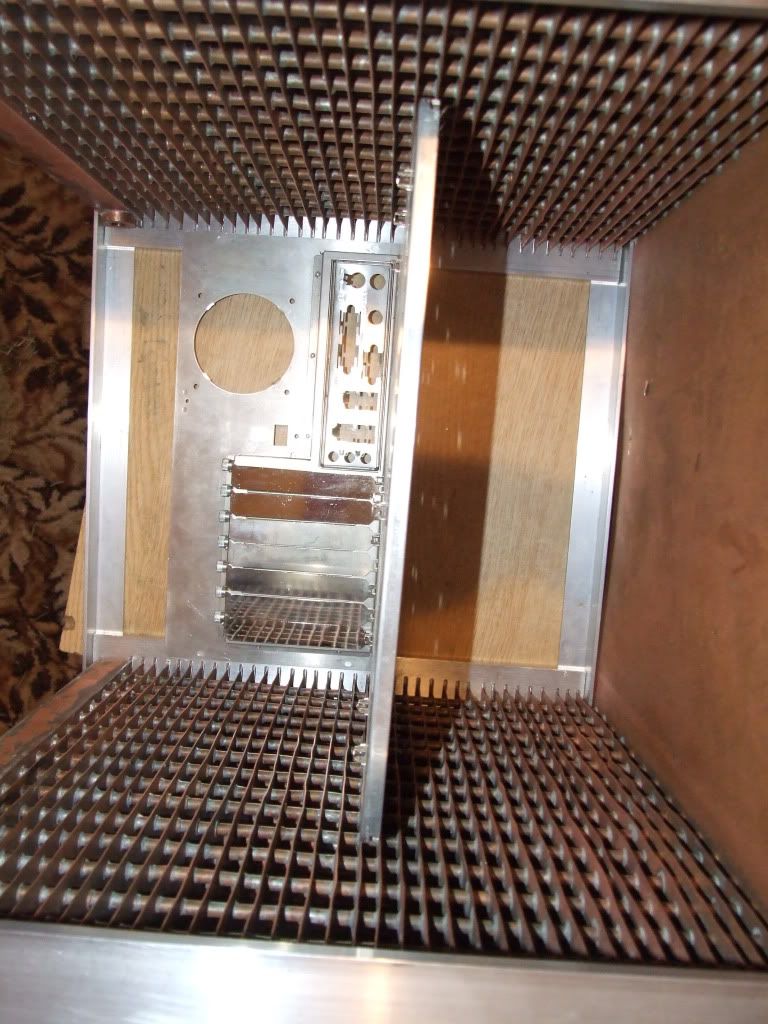
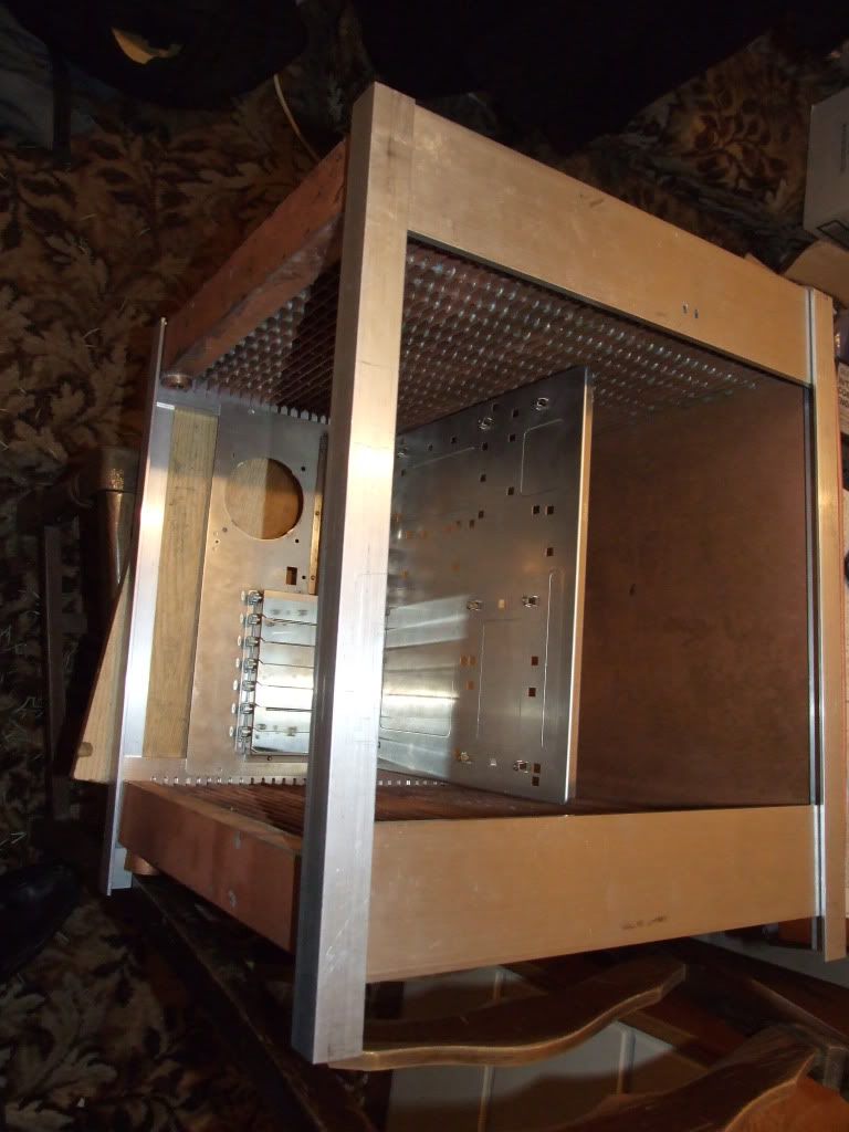
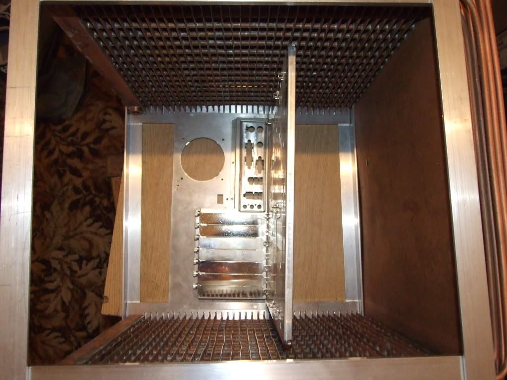
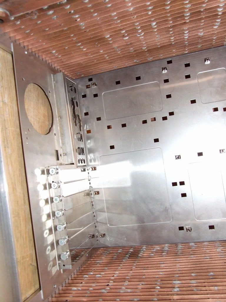
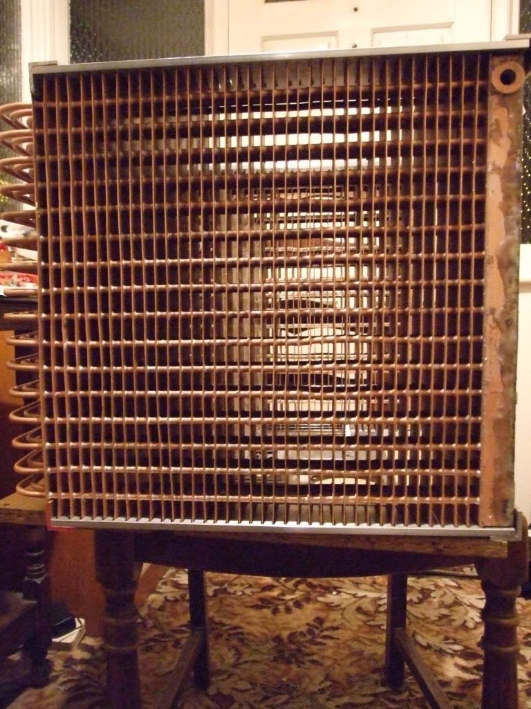
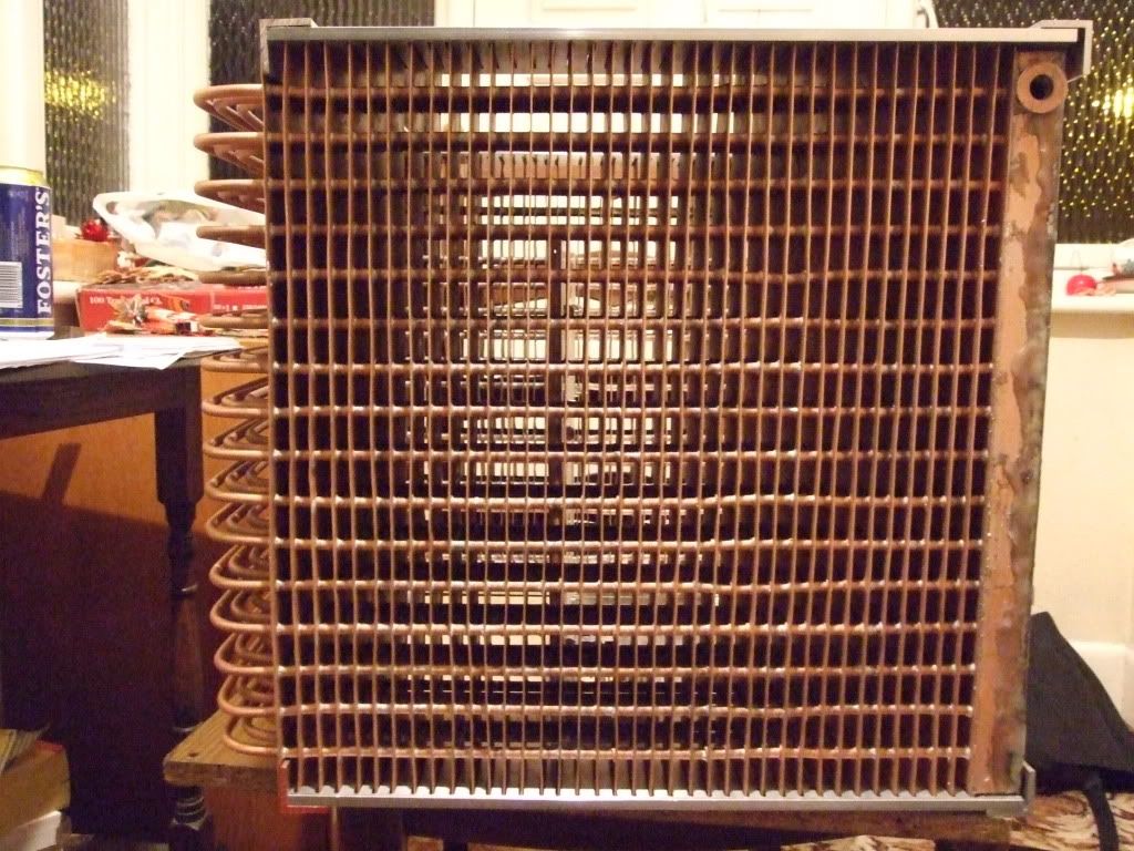
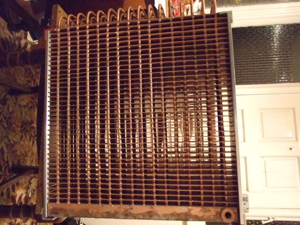
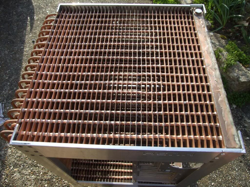
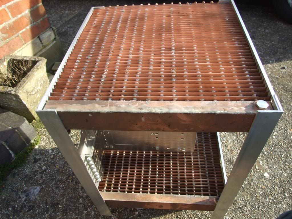
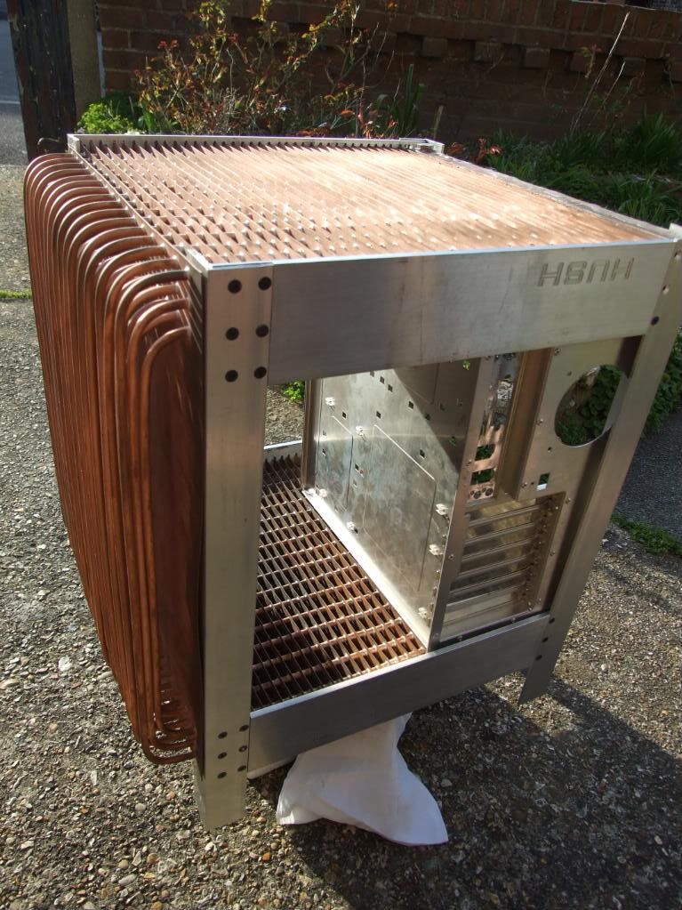
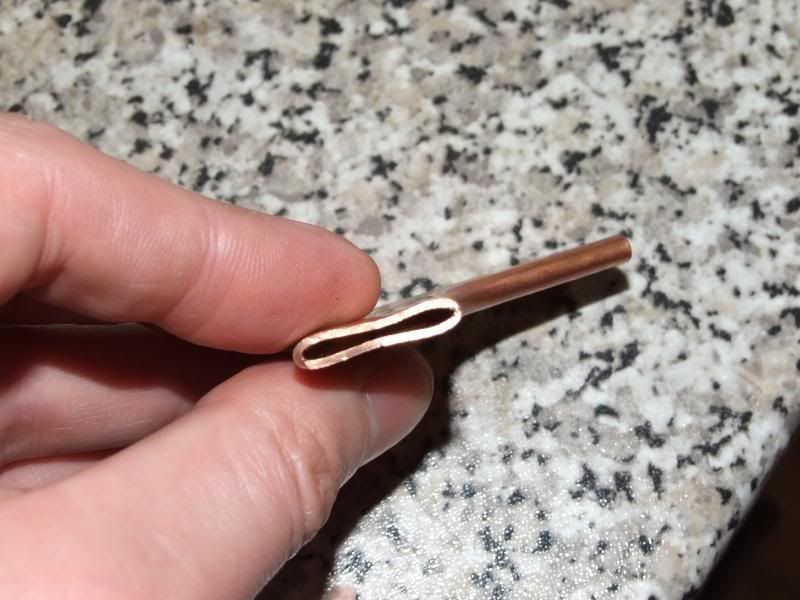
 Needs a bit of filing down to tidy up but getting there.