Help me find heat producing chips on my board

All about them.

Moderators: NeilBlanchard, Ralf Hutter, sthayashi, Lawrence Lee

Post Reply
Ollie`
Posts: 50
Joined: Sat Nov 19, 2005 10:38 pm
Location: Victoria BC

Help me find heat producing chips on my board

Post by Ollie` » Sat Nov 26, 2005 4:04 am

http://img.photobucket.com/albums/v202/ ... -board.jpg

GA-K8NS ^^

Im buying a bunch on mosfet heatsinks cuz they are cheap and im bored. Other then the 6 mosfets is there any other chip that creates alot of heat? I was going to replace the Northbridge sink but ... its not even hot (or really all that warm) to the touch after 9 hours of Prime95 (HTT is at 320). The mosfets i KNOW get hot .. not even gonna bother touching them :P

Thanks :P

justblair
Posts: 545
Joined: Fri Jul 15, 2005 12:33 pm
Location: GLASGOW, SCOTLAND, UK
Contact:

Post by justblair » Sat Nov 26, 2005 6:57 pm

I did this with my ABit NF7 board. Although mosfets get hot, I found that a light touch with a fingertip was enough to tell me how hot they were without hurting myself. In fact with the board sat on my desk powered up, just holding my finger a few mm's from the mossies I could sense the heat produced.

Go on get brave... :lol:

Ollie`
Posts: 50
Joined: Sat Nov 19, 2005 10:38 pm
Location: Victoria BC

Post by Ollie` » Sun Nov 27, 2005 1:53 am

Hehe .. Well i ordered 6 Mosfet sinks and some thermal adhesive last night. The other chips will have to wait :P

Do you have any pics of your install?

Ollie`
Posts: 50
Joined: Sat Nov 19, 2005 10:38 pm
Location: Victoria BC

Post by Ollie` » Mon Nov 28, 2005 11:36 am

Ill just sink em all!!


Image

justblair
Posts: 545
Joined: Fri Jul 15, 2005 12:33 pm
Location: GLASGOW, SCOTLAND, UK
Contact:

Post by justblair » Mon Nov 28, 2005 1:16 pm

Gonna try and get some photos. My bro's digital camera is out of batteries, going to charge some over the next few hours and try.

If I have joy I will post.

Blair

justblair
Posts: 545
Joined: Fri Jul 15, 2005 12:33 pm
Location: GLASGOW, SCOTLAND, UK
Contact:

Post by justblair » Tue Nov 29, 2005 2:42 pm

Ok.. Sorry for the wait.

1mbish file sizes ok for you?

http://uk.pg.photos.yahoo.com/ph/blairt ... pg&.src=ph

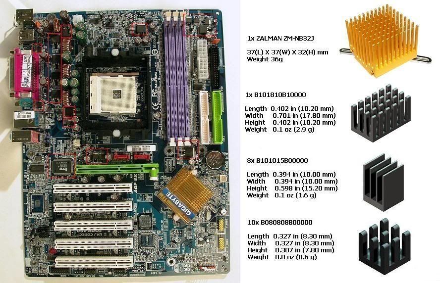
As you can see from the photo's I did not use purchased mosfet heatsinks but sliced up a couple of P2 heatsinks to do the job. The mosfets are covered by the light blue anodised sinks.

I am particularly happy with the array of six mosfets that are covered with two heatsinks. Best viewed in the third link. (bottom left of the shot) I shaped the sinks to fit around the caps. That section is the power regulator for the Vcore. These get the hottest, especially when I'm undervolting the vcore.

Also note next to the memory module there is a sink there, that mozzy regulates the memory core voltage. It gets hot if I up the memory voltages.

Just next to the AGP slot is a mozzy that regulates the video card, it barely gets warm, though I dont play games so I guess that voltage circuit never gets taxed.

I also used a anodised green heatsink for the southbridge chip

And my favourite is that gorgeous lump of copper is cooling the northbridge. Its a 6cm pure copper heatsink from evercool that I removed the fan bracket from and trimmed the fins on to make fit. It is attached with 2 screws and a couple of plastic home made spreaders on the underside. That gets warm when I undervolt the Vcore. I think that is because the TT typhoon stops blowing onto it (speedfan).

I also sinked the Winbond chip, you can just see that peeking out from under the typhoon in the second link if you look on the far left of the photo. It too can get a bit warm from time to time.

I have tt memory coolers installed. That is a great looking product by the way. A touch when the memory is overclocked tells me they do something, though its hard to quantify wether they make any difference. I bought them more because they came with heat transfering double sided tape. This is what I used to attach all those heatsinks.

I'm planning to add an akasa 8cm copper.alu heatsink to the graphics card in time.

The system is capable of running passive at 1000 mhz. I am building a case for it as we speak. Nearly finished, lots of mesh.

Oh and for comparison, this link takes you to a photo of the board in ots virgin state.

http://www.firingsquad.com/media/gallery_image.asp/91/1

Ollie`
Posts: 50
Joined: Sat Nov 19, 2005 10:38 pm
Location: Victoria BC

Post by Ollie` » Tue Nov 29, 2005 10:57 pm

Nice job :P

I could prolly make my own but id like to try and make it look factory installed..

http://www.thermaflo.com/bin/bgadatasht ... 1015b00000

justblair
Posts: 545
Joined: Fri Jul 15, 2005 12:33 pm
Location: GLASGOW, SCOTLAND, UK
Contact:

Post by justblair » Tue Nov 29, 2005 11:56 pm

Thanks Ollie.

I didn't count how many cutting disks I went through to cut the complex shapes, so yes using factory formed ones would definately be easier.

I have to say, I did enjoy the 3 hours or so it took me to do it, (how sad am I?) strangely therapeutic.... it was the 1st centuary equivalent to whittling. :)

At the time I took vcore readings before and after, it did smooth out the vcore graph a bit. As I intend running this board passive at least some of the time, it should make a small difference to reliabilty.

For the couple of quid I invested in the process, I dont think that it broke the bank and was probably a reasonable investment.

Post Reply