
If in fact it is passive, there will be no pump.Cistron wrote:*whistles* Metal works always stun me in awe. However, let's see how loud the pump will be.
Project: Hush!
Moderators: NeilBlanchard, Ralf Hutter, sthayashi, Lawrence Lee
Amazing piece of work, hats off!

Anyway, looking forward to see the beast in action
He did mention a pump so I think passive refers to a lack of fans. I`m also curious to see how loud the pump will be. If I did a water cooling setup I would suspend the pump in waterIf in fact it is passive, there will be no pump.
Anyway, looking forward to see the beast in action
-
Monkey Puzzle
- Posts: 37
- Joined: Tue Apr 13, 2010 5:14 am
- Location: UK
cheers for the nice comments guys.
The weight of it empty is around 25kg. It doesn't actually hold that much water since the copper pipes are only 4.8mm inner diameter. The tubes themselves hold in total just under 900ml and the two copper end boxes/plenums each hold around 400ml, so all in all about 1.7 litres in total. Should weigh around 34-35kg when everything's installed. It's heavy but not too unmanageable.
Ces - The pump is a 10w laing ddc pump. It's very quiet - almost all the noise it makes is from transmitted vibrations, so it's annoyingly noisy sat on a hard surface but indistinguishable from ambient noise from around 10cm or so away when soft mounted sat on foam/petras gel stuff block. Quieter than a 12cm yate loon low model undervolted to 6-7v in my experience. The only fan is the sanyo denki san ace pwm on the seasonic x750, which occasionally flicks on when gaming or stability testing, but doesn't spin at all when browsing or watching films etc.
Can you post pictures of the finished product?Monkey Puzzle wrote:Ces - The pump is a 10w laing ddc pump. It's very quiet - almost all the noise it makes is from transmitted vibrations, so it's annoyingly noisy sat on a hard surface but indistinguishable from ambient noise from around 10cm or so away when soft mounted sat on foam/petras gel stuff block. Quieter than a 12cm yate loon low model undervolted to 6-7v in my experience. The only fan is the sanyo denki san ace pwm on the seasonic x750, which occasionally flicks on when gaming or stability testing, but doesn't spin at all when browsing or watching films etc.
-
Monkey Puzzle
- Posts: 37
- Joined: Tue Apr 13, 2010 5:14 am
- Location: UK
the last pictures I posted were where the project is up to. The components are not installed - I'm running the pc on a desk top atm using a 120.2 radiator and the 5400rpm samsung eco 1.5tb hd and ssd. I've done leak/flowrate testing which gives a good indication of final noise levels, which are nice. It does sound like someone is drumming it with spoons whilst the radiator bleeds itself of air though. 
You sir, just made my day. Copper makes me drool, especially this much. This is beautiful craftmanship, but I foresee a big problem. Since the copper fins are below the case, the heat rising from it will move past the components, warming them up again. I don't think it'll make the whole circuit very effective...
it's not like that's gonna make that much of a difference.Xobim wrote:You sir, just made my day. Copper makes me drool, especially this much. This is beautiful craftmanship, but I foresee a big problem. Since the copper fins are below the case, the heat rising from it will move past the components, warming them up again. I don't think it'll make the whole circuit very effective...
Project HUSH
I'm in awe of your dedication and skill to the silent task! I've registered as a result! And I thought changing my fans and adding a controller was an 'upgrade'. . . . . (I'm currently considering watercooling). But on this scale I would put the pc in the kid's room and run extended keyboard, mouse and monitor cables through the wall into my pc room next door!
-
Monkey Puzzle
- Posts: 37
- Joined: Tue Apr 13, 2010 5:14 am
- Location: UK
Glad you like it.Xobim wrote:You sir, just made my day. Copper makes me drool, especially this much. This is beautiful craftmanship, but I foresee a big problem. Since the copper fins are below the case, the heat rising from it will move past the components, warming them up again. I don't think it'll make the whole circuit very effective...
Last edited by Monkey Puzzle on Fri May 07, 2010 11:16 am, edited 2 times in total.

-
matt_garman
- *Lifetime Patron*
- Posts: 541
- Joined: Sun Jan 04, 2004 11:35 am
- Location: Chicago, Ill., USA
- Contact:
That is amazing... It seems to me that silent computing gets easier every year, so we see fewer and fewer of these crazily ambitious projects. So when we do see someone go to these kinds of lengths, it's that much more of a treat! A lot of that work looks quite tedious---may no one ever question your patience.
I've always wondered if you could do something like this using a car radiator. I suppose a car radiator is designed for high air flow (and has a massive, fast, loud fan for when the car isn't moving). But then again, I assume even the smallest internal combustion engine generates significantly more heat than any computer component.
So the next evolution in this idea is to build a massive radiator and fan assembly. I.e. the kind of cooling package you'd have on a giant diesel engine. Put that outside your house, and run the cooling circuit to every room in your house (right along your 100 GigE network lines ). Now, whenever you build a PC, you just plug in your water cooling lines to the ports you have in every room.
I've always wondered if you could do something like this using a car radiator. I suppose a car radiator is designed for high air flow (and has a massive, fast, loud fan for when the car isn't moving). But then again, I assume even the smallest internal combustion engine generates significantly more heat than any computer component.
So the next evolution in this idea is to build a massive radiator and fan assembly. I.e. the kind of cooling package you'd have on a giant diesel engine. Put that outside your house, and run the cooling circuit to every room in your house (right along your 100 GigE network lines
-
Monkey Puzzle
- Posts: 37
- Joined: Tue Apr 13, 2010 5:14 am
- Location: UK
Thanks for the nice comments. It has taken a lot of work so far- god knows how many hours, and there's still quite a lot to go.
Performance is fairly good - cooling the i750 cpu overclocked at 4GHz (vcore 1.3-1.35, speedstep off) it was idling at 24-26c during the morning of a warm day (ambient 20c?) and around 34-35 in the afternoon (ambient 30c ish in a hot sun-facing room with a large tropical fishtank). Load temps stabilised with overclocking stability testing programs were 62c with occt and 70-72c with intel burn test (on maximum stress, on several hundred cycles).
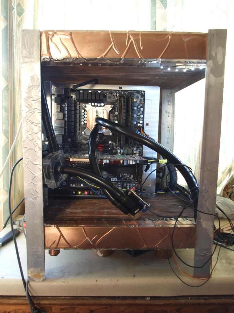
The funny plasticky look is because the copper boxes/plenums have had polyester resin cast around them to ensure they're watertight. The mold was made from acrylic sheet, and I left the protective film on... As the resin hardens it shrinks slightly, and it pulled the protective sheet away causing 1mm deep ripples. I'm going to sand and polish them flat.
Performance is fairly good - cooling the i750 cpu overclocked at 4GHz (vcore 1.3-1.35, speedstep off) it was idling at 24-26c during the morning of a warm day (ambient 20c?) and around 34-35 in the afternoon (ambient 30c ish in a hot sun-facing room with a large tropical fishtank). Load temps stabilised with overclocking stability testing programs were 62c with occt and 70-72c with intel burn test (on maximum stress, on several hundred cycles).
The funny plasticky look is because the copper boxes/plenums have had polyester resin cast around them to ensure they're watertight. The mold was made from acrylic sheet, and I left the protective film on... As the resin hardens it shrinks slightly, and it pulled the protective sheet away causing 1mm deep ripples. I'm going to sand and polish them flat.
-
Monkey Puzzle
- Posts: 37
- Joined: Tue Apr 13, 2010 5:14 am
- Location: UK
Time for an update!
(Photos taken on my n97 so not the best quality I'm afraid.)
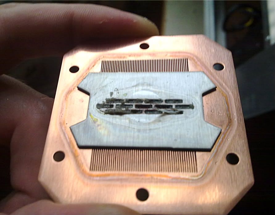
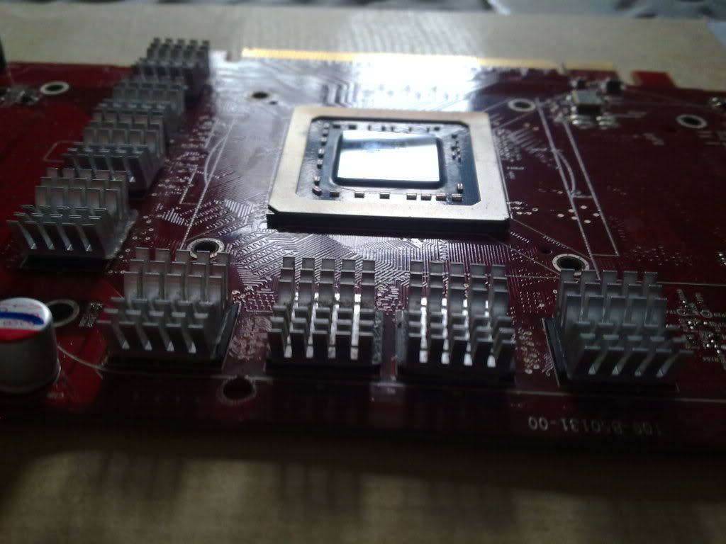
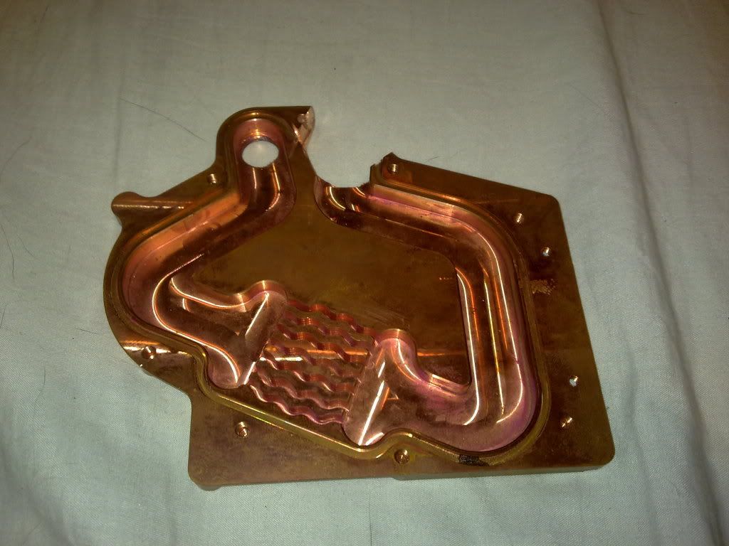
First, I decided to attach the GPU block to the GPU. I bled the loop to take the tubes offf the block, and decided to open the CPU block whilst I was at it...
And this is what I found - lots of resin gunk must have come off when I degunked the top fill-port thread (more of that in a minute) and so the previous temperature testing was done with water only flowing into about 1.5 of the 12 impingement slits, cooling only two narrow strips about 5mm wide.
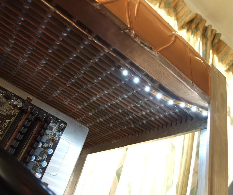
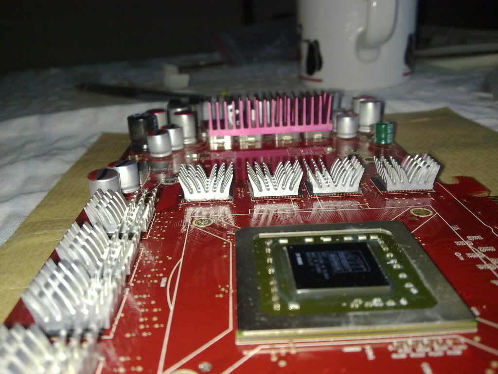
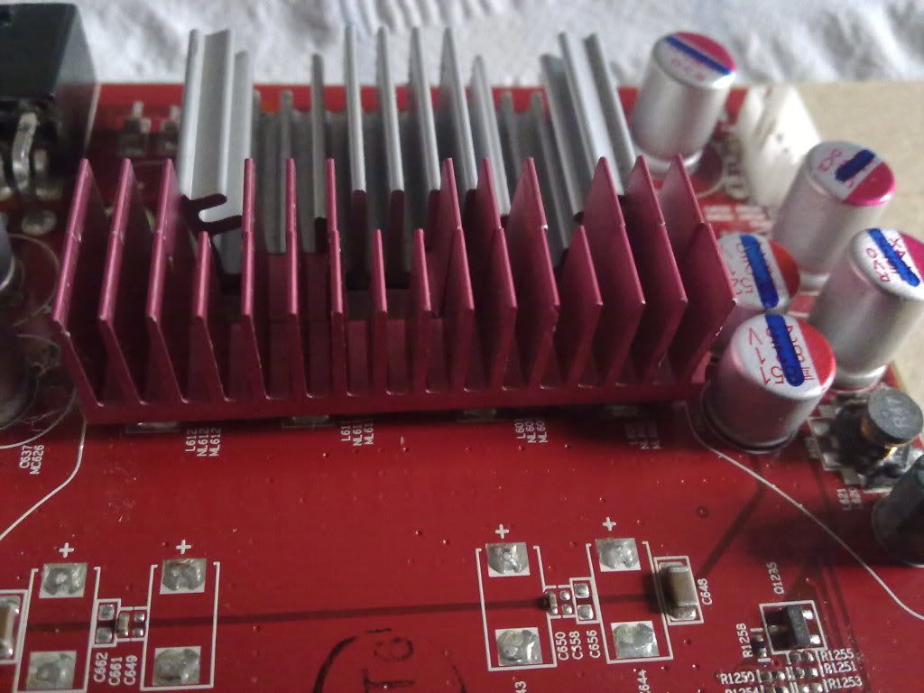
I then added the graphics RAM heatsinks. I was going to cannibalise the single-slot stock cooler on my 4850 as it has nice big sections of widely spaced tall copper pins to cool the VRMs. Except after dremeling about a mm into the stock cooler I realised the stock cooler was just aluminium anodised with copper-coloured dye. Damned charlatans!
So instead I opted to cannibalise an old VRM heatsink from my old x1900xt (the pinky-crimson coloured bits) as they're widely spaced fins an nice and tall, combined with an aluminium heatsink that's supposed to go onto 8800gtx VRMs I think.
(Photos taken on my n97 so not the best quality I'm afraid.)
First, I decided to attach the GPU block to the GPU. I bled the loop to take the tubes offf the block, and decided to open the CPU block whilst I was at it...
And this is what I found - lots of resin gunk must have come off when I degunked the top fill-port thread (more of that in a minute) and so the previous temperature testing was done with water only flowing into about 1.5 of the 12 impingement slits, cooling only two narrow strips about 5mm wide.
I then added the graphics RAM heatsinks. I was going to cannibalise the single-slot stock cooler on my 4850 as it has nice big sections of widely spaced tall copper pins to cool the VRMs. Except after dremeling about a mm into the stock cooler I realised the stock cooler was just aluminium anodised with copper-coloured dye. Damned charlatans!
So instead I opted to cannibalise an old VRM heatsink from my old x1900xt (the pinky-crimson coloured bits) as they're widely spaced fins an nice and tall, combined with an aluminium heatsink that's supposed to go onto 8800gtx VRMs I think.
-
Monkey Puzzle
- Posts: 37
- Joined: Tue Apr 13, 2010 5:14 am
- Location: UK
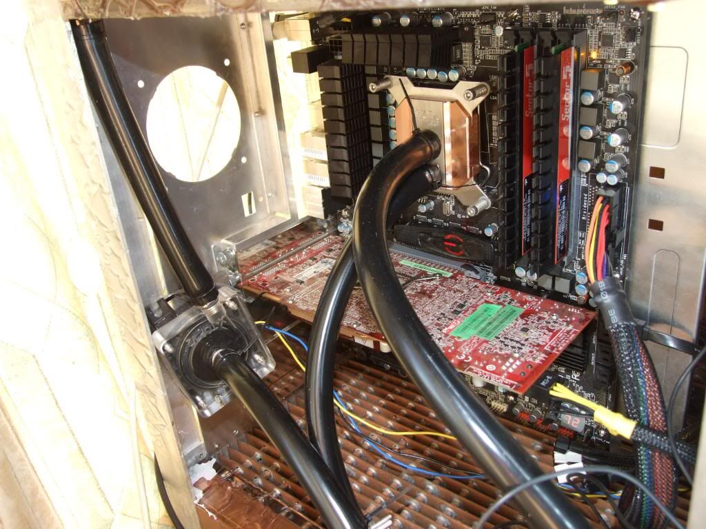
I then replumbed the loop, started the machine up and did some more temperature testing....
With a degunked HK3.0 waterblock and with the 4850 GPU also in the loop, with the core i750 at 4.2Ghz using 1.43volts vcore it was maxing out at about 55C running intel burn test with the maximum stress I could (about 3.5GB of RAM). During gaming (Arma II) it maxed out at around 50C.
Previously, with just the CPU in the loop it had been reaching 72 in intel burn test in my toasty room.
It idles slightly higher now after degunking but with the GPU in the loop, at around 30-32C compared to 26c before.
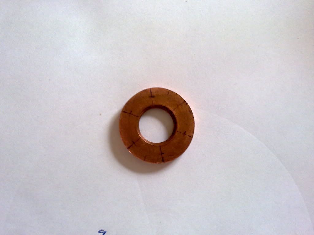
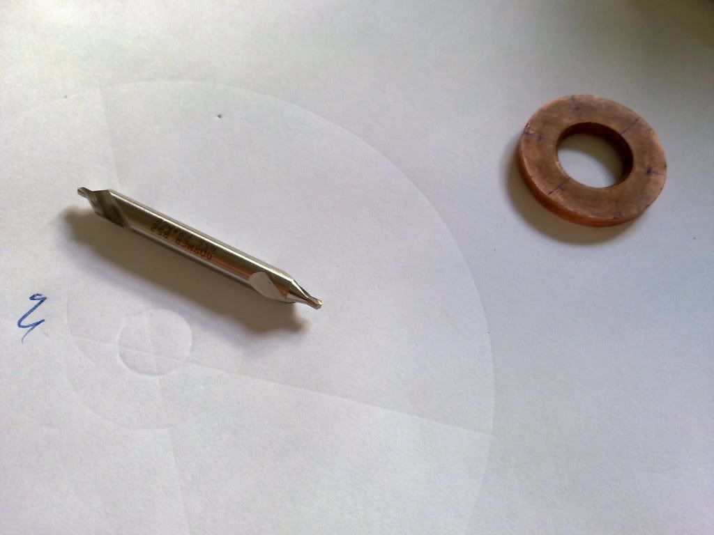
Sadly, a minor disaster struck. When I cast the thick polyester resin over the top and bottom manifolds/plenums, some resin had managed to find its way under the mold top glued to the top fill-port, and a little bit into the screw thread for the fill cap. I'd tried to dissolve it out using acetone on cotton buds, but with no joy. I stupidly decided to try scraping it out, and in doing so the thread got a bit worn and slightly mangled. Then when I tried to screw in the top fill-port plug it was really tricky to get it to seal, and I needed to screw it in really tight. Then I screwed it in too tight, heard creaking, and the copper fill-port (the 1" diameter x ~5mm cooper ring with the thread inside) sheared at the soldered joint attaching it to the 1mm thick copper wall of the plenum, like so:
PIC SHEARED FILLPORT
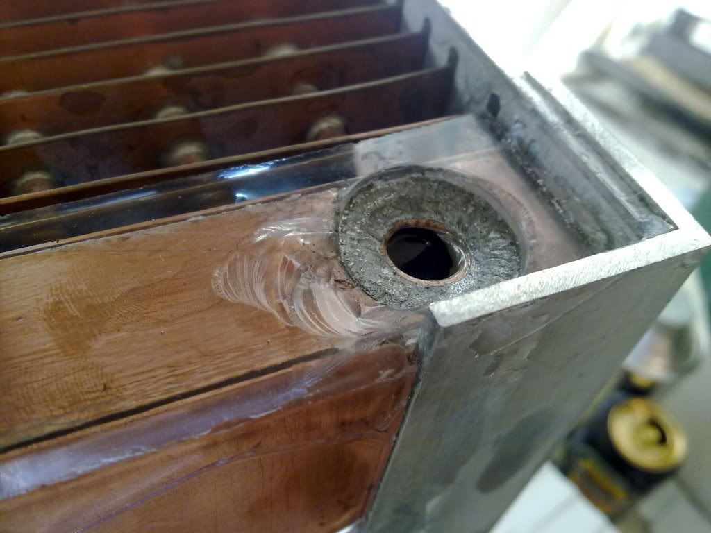
It will be fixable, and I'll recast resin into the bits where shards have come off...
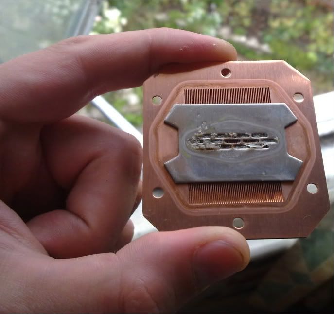
So then I did a horrible thing to a very pretty waterblock. As I didn't have access to a lathe or a 11mm odd drill bit, I decided to cannibalise an EK x1900xt fullcover copper waterblock to make a replacement fillport...
pic cannibalised waterblock
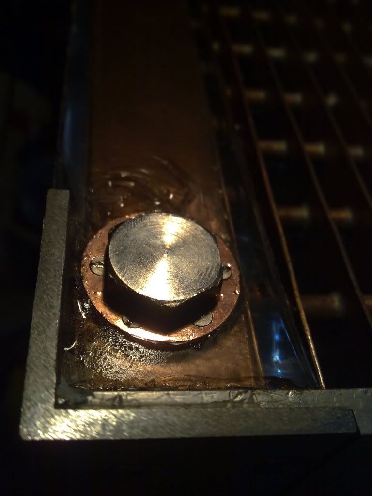
After a bit of filing and sanding I was left with this; a shiny new fillport.
With a degunked HK3.0 waterblock and with the 4850 GPU also in the loop, with the core i750 at 4.2Ghz using 1.43volts vcore it was maxing out at about 55C running intel burn test with the maximum stress I could (about 3.5GB of RAM).
Previously, with just the CPU in the loop it had been reaching 72 in intel burn test in my toasty room.
It idles slightly higher now after degunking but with the GPU in the loop, at around 30-32C compared to 26c before.
Sadly, a minor disaster struck. When I cast the thick polyester resin over the top and bottom manifolds/plenums, some resin had managed to find its way under the mold top glued to the top fill-port, and a little bit into the screw thread for the fill cap. I'd tried to dissolve it out using acetone on cotton buds, but with no joy. I stupidly decided to try scraping it out, and in doing so the thread got a bit worn and slightly mangled. Then when I tried to screw in the top fill-port plug it was really tricky to get it to seal, and I needed to screw it in really tight. Then I screwed it in too tight, heard creaking, and the copper fill-port (the 1" diameter x ~5mm cooper ring with the thread inside) sheared at the soldered joint attaching it to the 1mm thick copper wall of the plenum, like so:
PIC SHEARED FILLPORT
It will be fixable, and I'll recast resin into the bits where shards have come off...
So then I did a horrible thing to a very pretty waterblock. As I didn't have access to a lathe or a 11mm odd drill bit, I decided to cannibalise an EK x1900xt fullcover copper waterblock to make a replacement fillport...
pic cannibalised waterblock
After a bit of filing and sanding I was left with this; a shiny new fillport.
-
Monkey Puzzle
- Posts: 37
- Joined: Tue Apr 13, 2010 5:14 am
- Location: UK
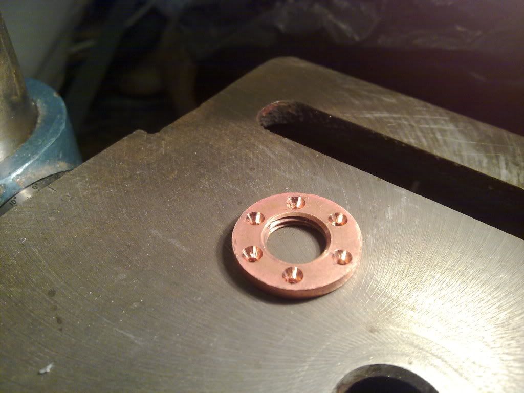
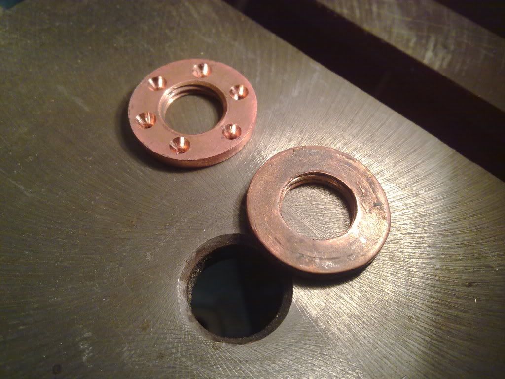
However, there's now resin covering the plenum, so it can't be soldered on. I didn't want to risk it coming off again so I bought a 2mm countersunk drill bit and some m2 countersunk screws, and set at it with my weedy bench drill.
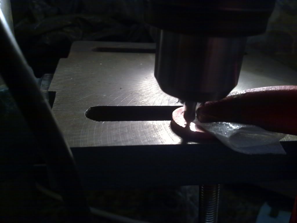
Here's a comparison of the thread on the old and new fill-port:
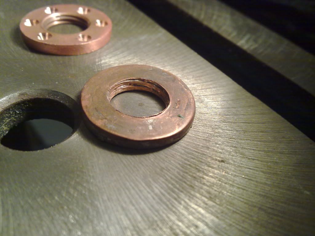
With 6 screws attaching the fillport to the 1mm thick copper wall it should be able to resist being screwed in.
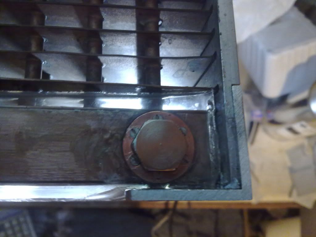
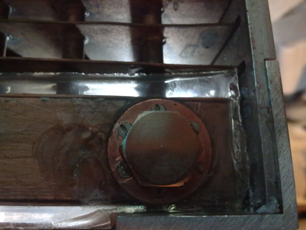
So that's where it's up to at the moment.
Here's a comparison of the thread on the old and new fill-port:
With 6 screws attaching the fillport to the 1mm thick copper wall it should be able to resist being screwed in.
So that's where it's up to at the moment.
-
frostedflakes
- Posts: 1608
- Joined: Tue Jan 04, 2005 4:02 pm
- Location: United States
-
Monkey Puzzle
- Posts: 37
- Joined: Tue Apr 13, 2010 5:14 am
- Location: UK
UPDATE!
Update time!
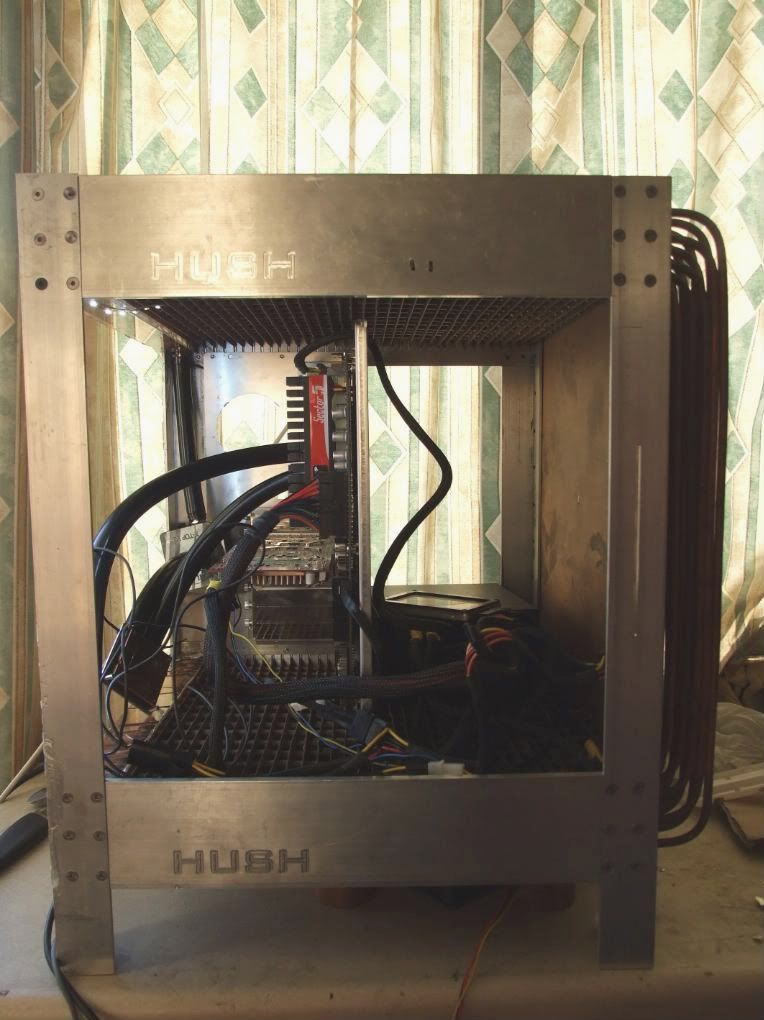
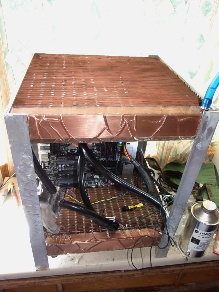
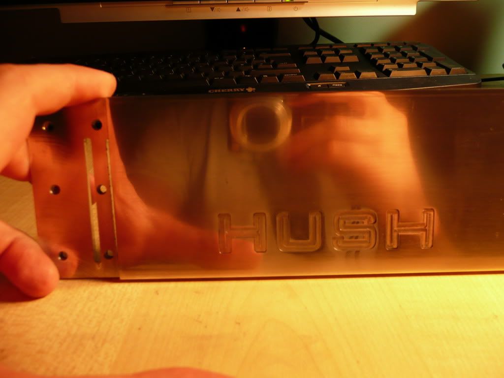
Not a massive update, but took quite a bit of time. I've been tidying up the aluminium frame. It had been covered in polyester resin, which was a nightmare to get rid of. I've sanded the frame down , though it still needs more work and there are still some small blemishes and scratches that I need to get rid of. I'm not 100% how necessary a mirror-shine is, since I plan on anodising the frame either gun-metal/carbon grey or black.
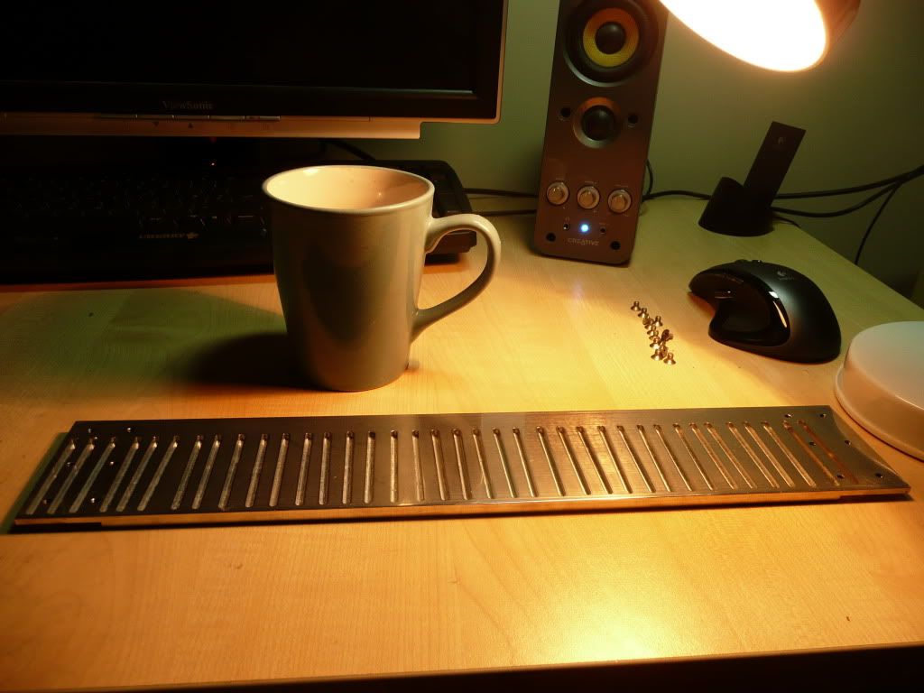
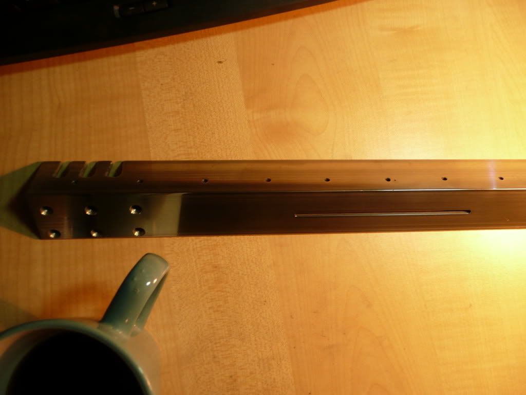
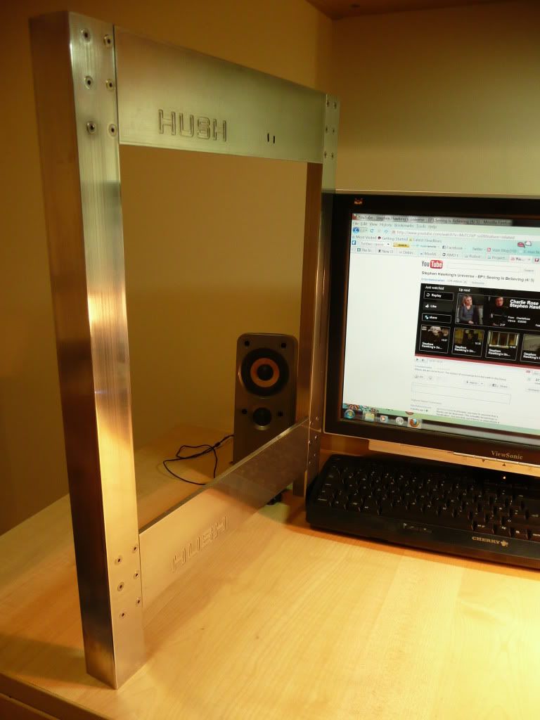
Anyhow, here's some pictures. Enjoy!
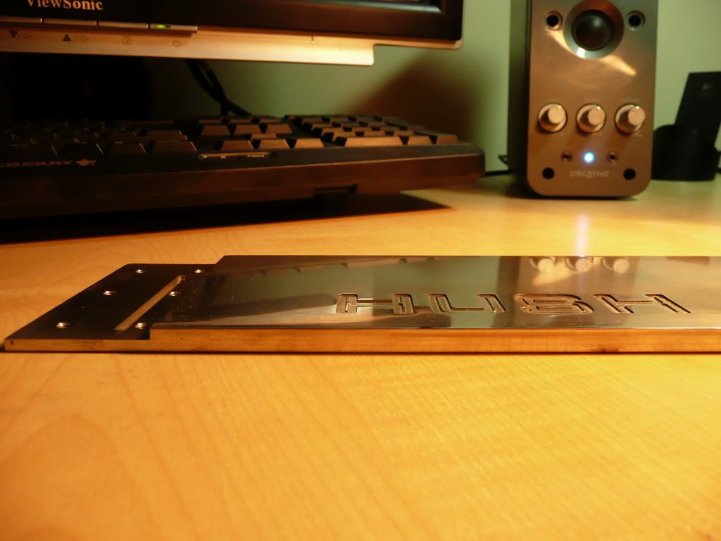
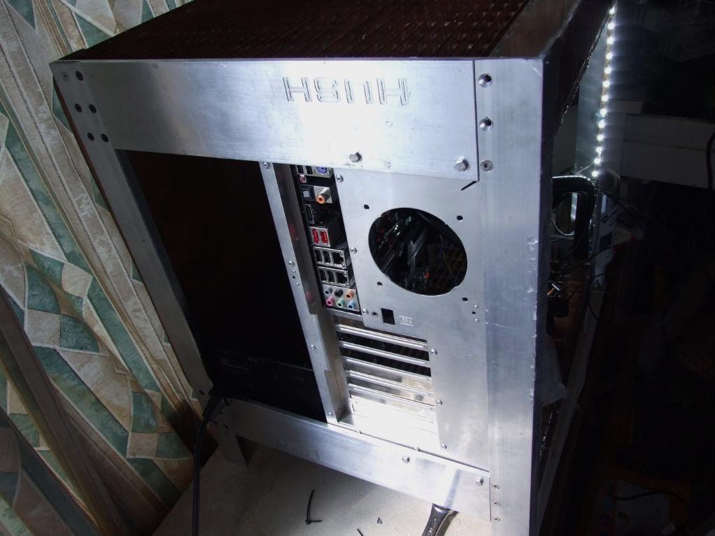
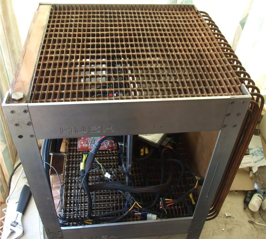
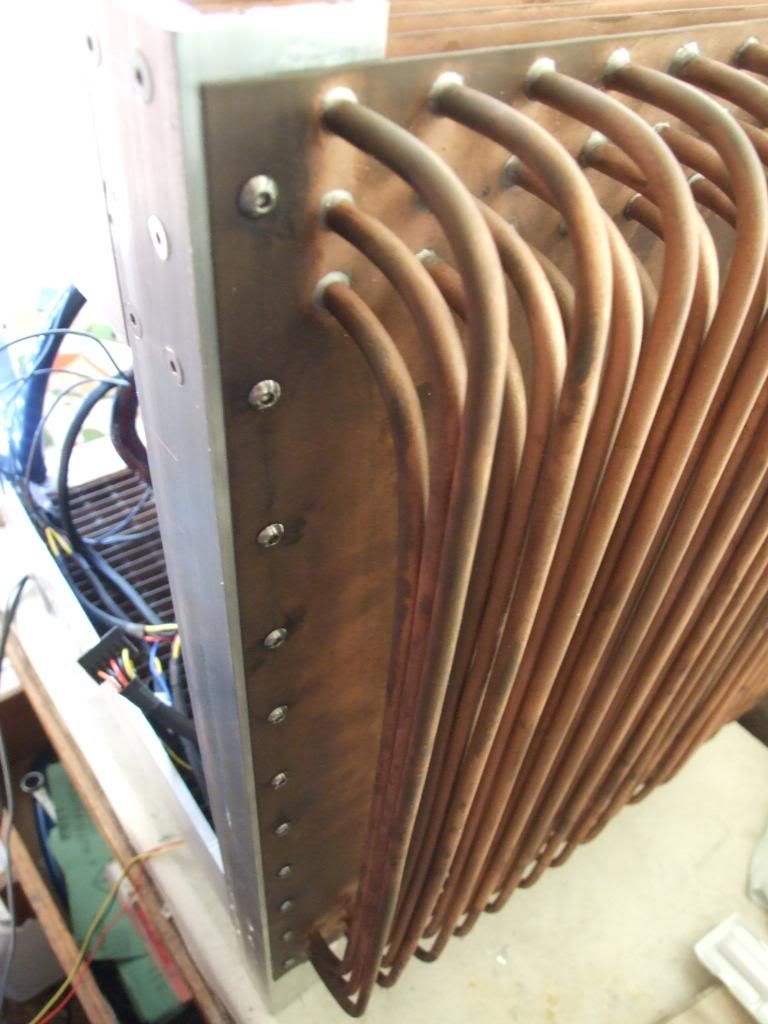
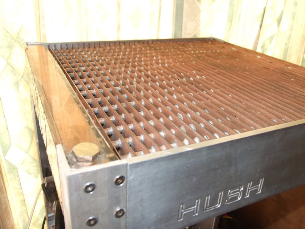
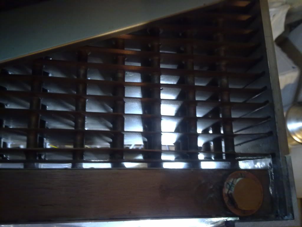
And here's the back of it. The slits are for the 37 copper heatfins to sit in. They'll later be set into these groves, probably using polyester resin.
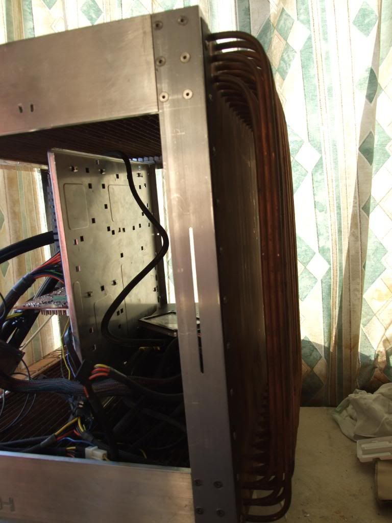
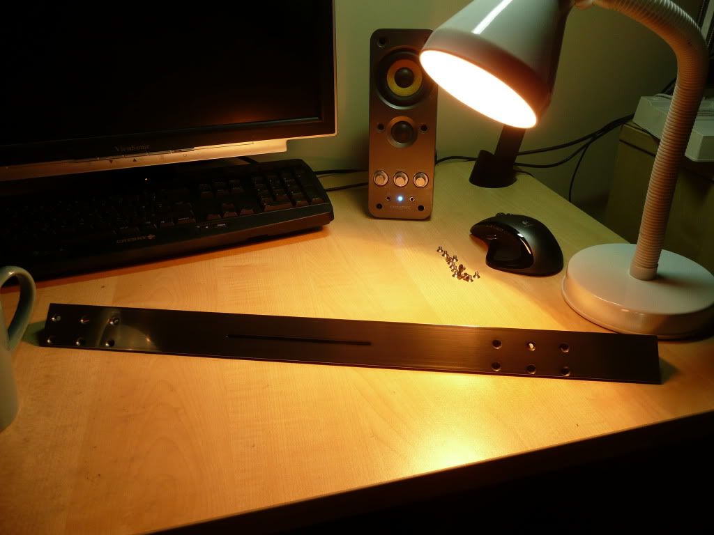
Here's the right-sided upright aluminium angle leg. The row of 9 holes is to attach to the copper wall of the radiator. The 3 finger cuts set into the top and bottom are to accommodate the copper pipes of the radiator.
The slit is for a slimline slot-loading DVD drive to sit behind. Still planning on a no-5.25" design for the front.
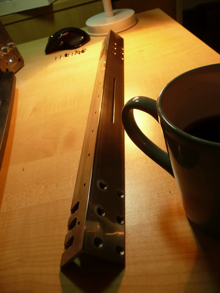
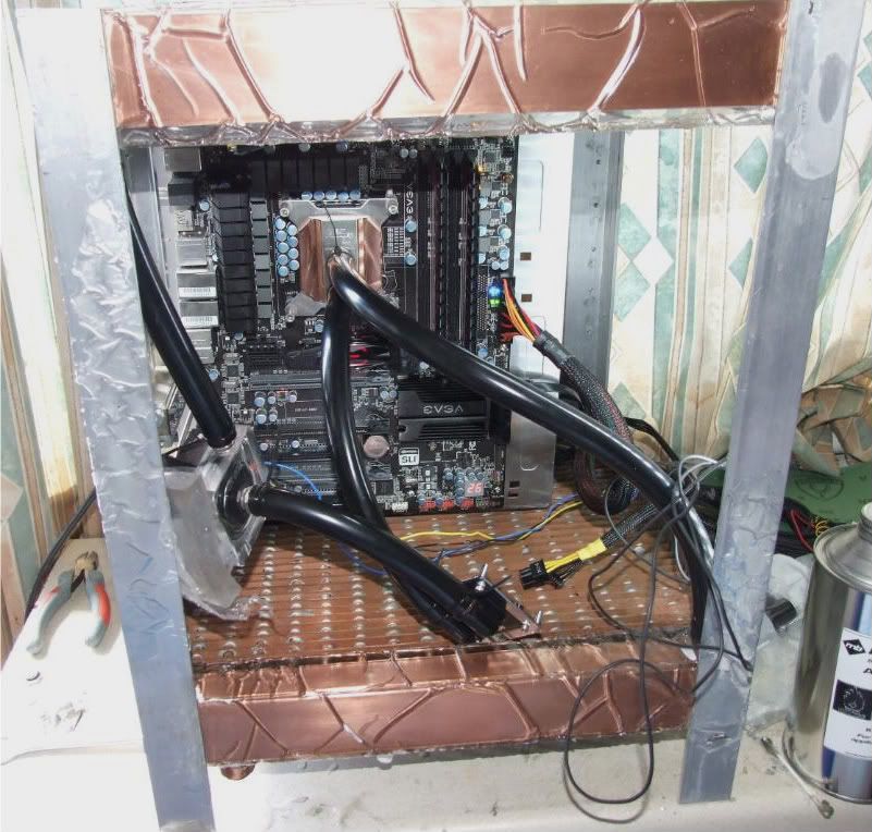
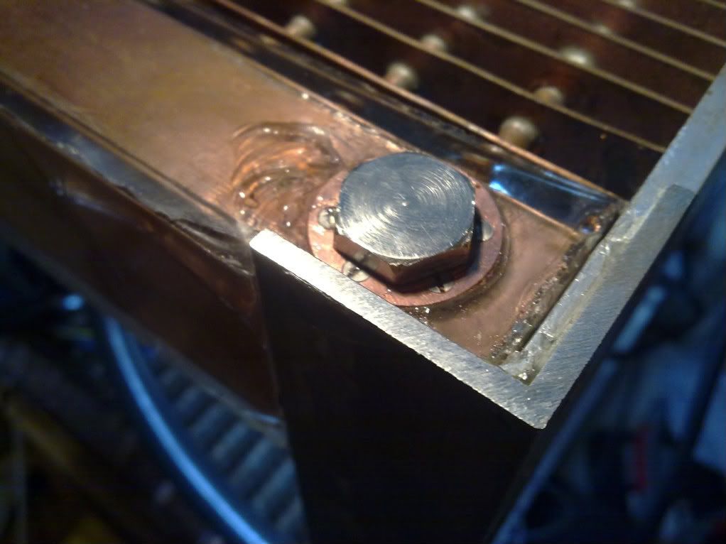
Here it is with the counter-sunk screws in. The one on the bottom left is stuck in place - think I must have forgotten to tap all the way through and it's got caught in the aluminium. I'll have to drill it out on the bench press next time I go visit my folks. Until then I can't sand around it or disassemle those two pieces. I still need to adjust the countersunk holes slightly to get the screws exactly flush, but most of them are level with the surface.
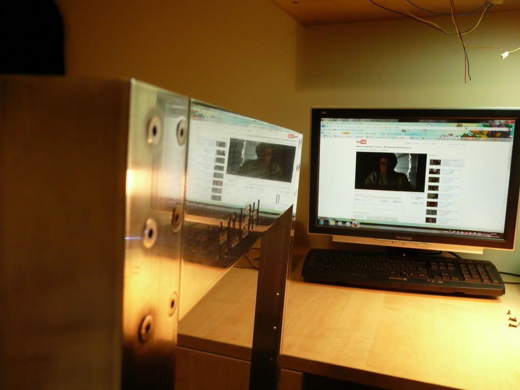
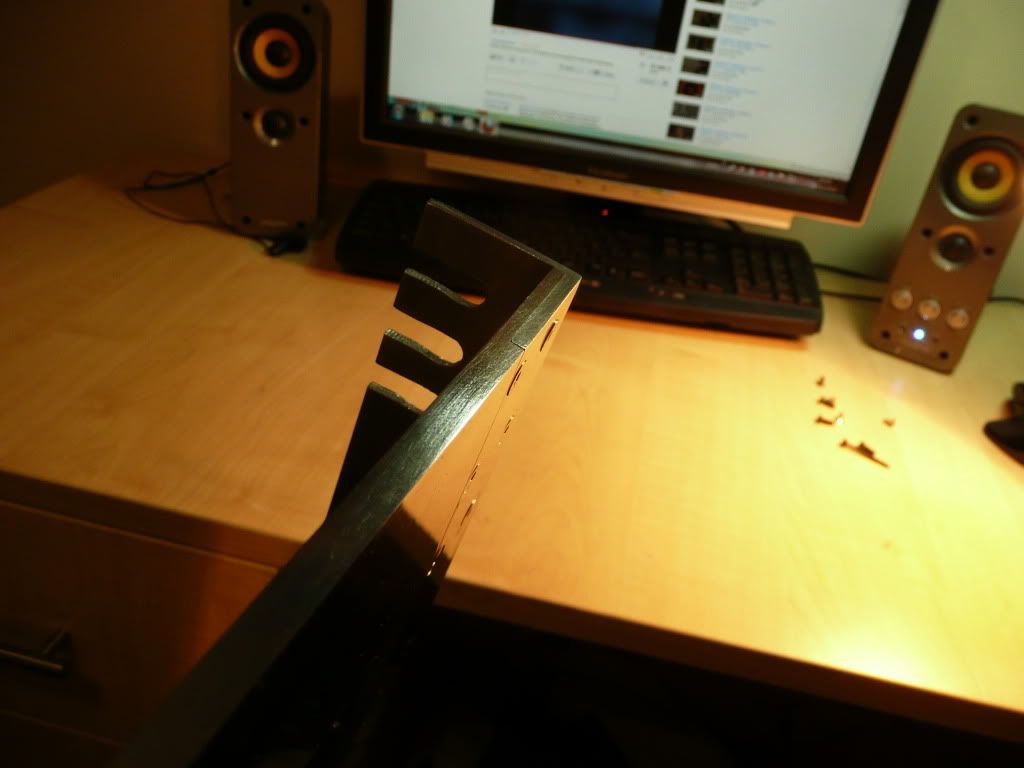
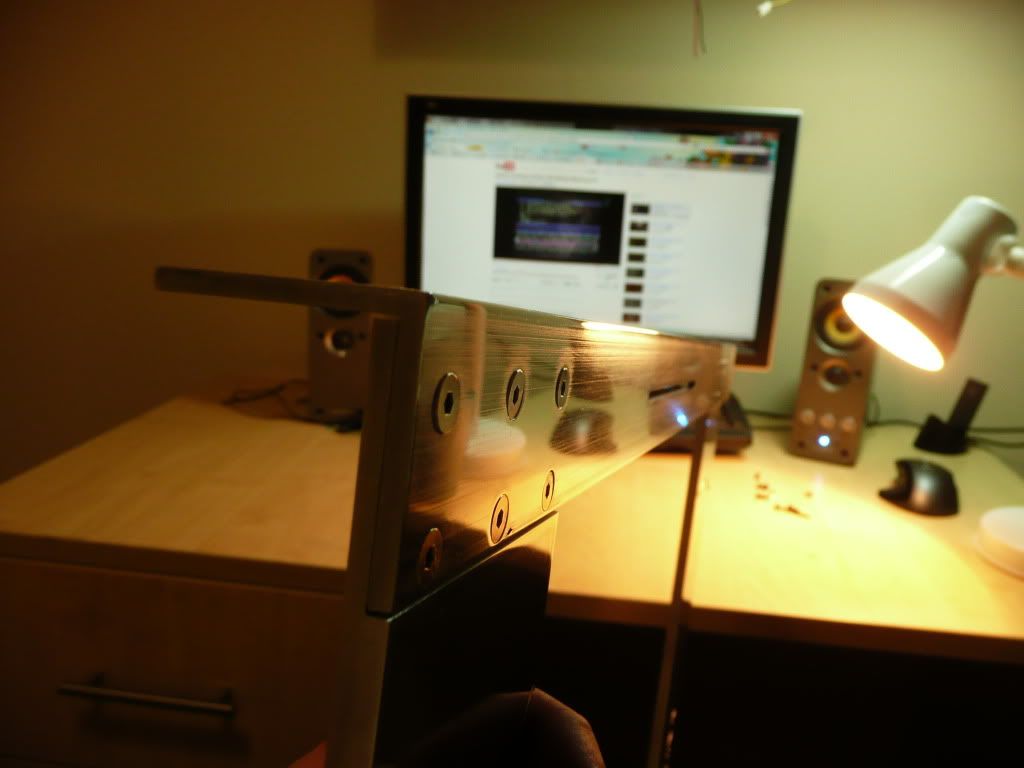
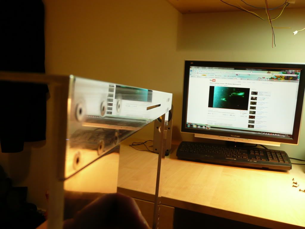
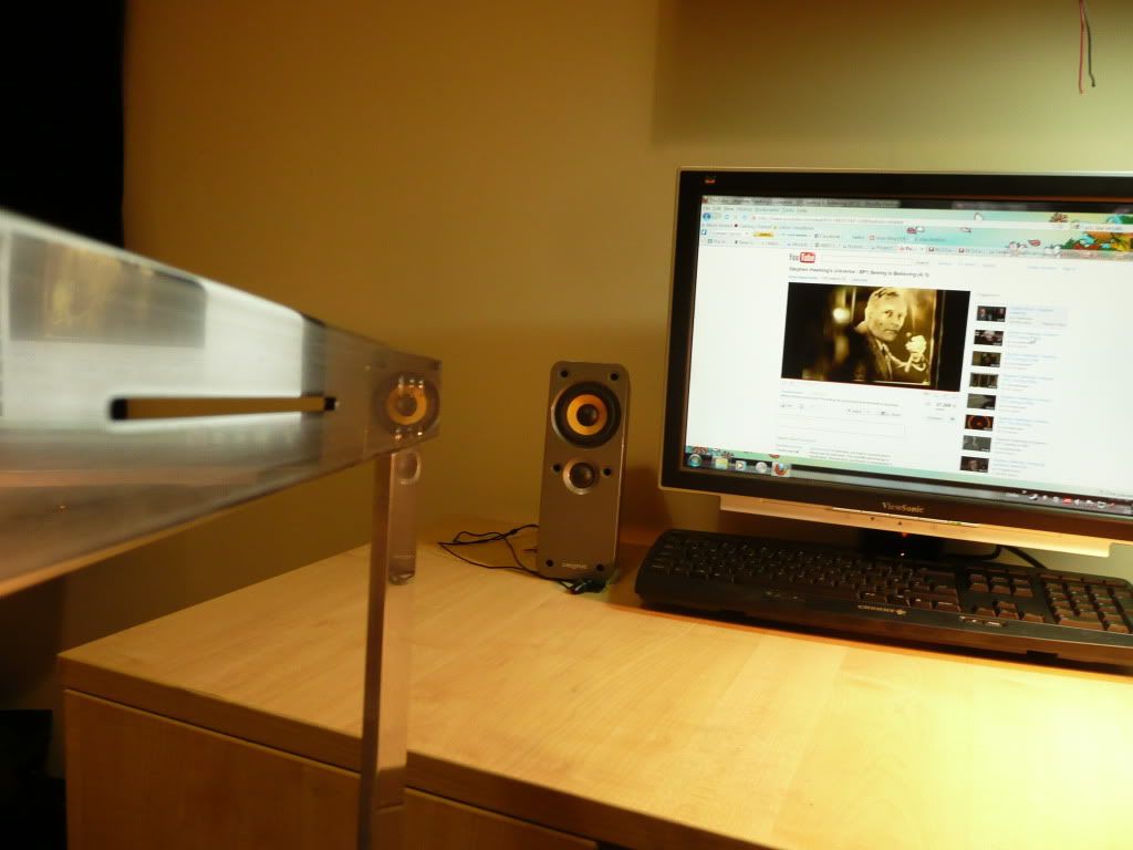
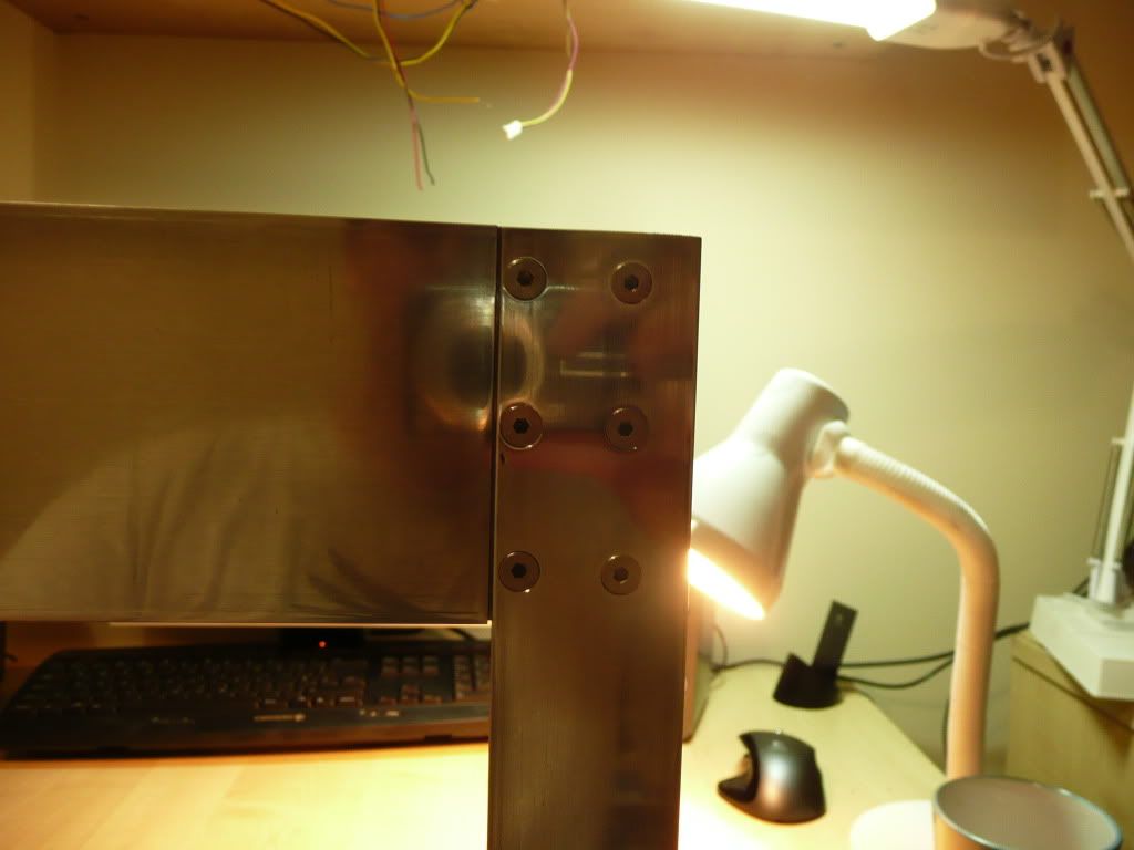
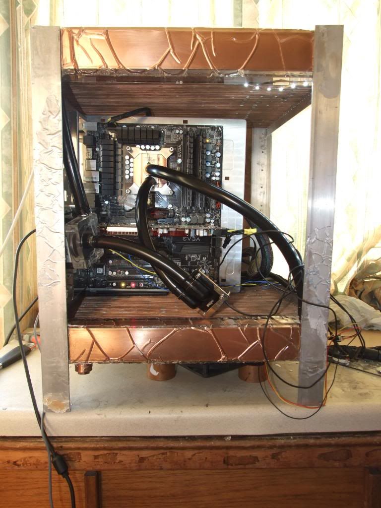
And here it is assembled:
Might take some better photos later on.
Not a massive update, but took quite a bit of time. I've been tidying up the aluminium frame. It had been covered in polyester resin, which was a nightmare to get rid of. I've sanded the frame down , though it still needs more work and there are still some small blemishes and scratches that I need to get rid of. I'm not 100% how necessary a mirror-shine is, since I plan on anodising the frame either gun-metal/carbon grey or black.
Anyhow, here's some pictures. Enjoy!
And here's the back of it. The slits are for the 37 copper heatfins to sit in. They'll later be set into these groves, probably using polyester resin.
Here's the right-sided upright aluminium angle leg. The row of 9 holes is to attach to the copper wall of the radiator. The 3 finger cuts set into the top and bottom are to accommodate the copper pipes of the radiator.
The slit is for a slimline slot-loading DVD drive to sit behind. Still planning on a no-5.25" design for the front.
Here it is with the counter-sunk screws in. The one on the bottom left is stuck in place - think I must have forgotten to tap all the way through and it's got caught in the aluminium.
And here it is assembled:
Might take some better photos later on.