
Hey everyone,
I'm new to the forums thanks to the ASUS Xtreme Design Contest.
I am here now after winning stage 1, to present you the stage 2 build blog. I will be posting pictures and stories of the build here, as well as a blog I have set up.
If you are looking for the blog, please see: http://www.xtremebuild.info
I will be mirroring posts between the blog and here, feel free to leave comments on either.
I will begin cross posting today, my posts will all be in this thread.
ASUS Xtreme Design contest - Stage 2 – fps randy
Moderators: NeilBlanchard, Ralf Hutter, sthayashi, Lawrence Lee
ASUS Xtreme Design contest - Stage 2 – fps randy
Last edited by fpsrandy on Mon Nov 30, 2009 4:02 pm, edited 1 time in total.
Introduction
So as an introduction to this blog, I will introduce myself. My name is Randy. I would normally hide my identity, but as this blog is part of a requirement of the Xtreme Design Contest (Hosted by ASUS) for Stage 2; so I'll throw some caution to the wind.
My gamer handle varies; I have been known on the internet as: Dude, Minimum Infinity, EyeKanSpele, Randay, Sharri (World of Warcraft, I played as a female Draeni), Randie (I later server transferred and decided to switch names), and fps randy. Generally I like to keep my handles pretty common, you never know who may be lurking on the internet...
Anyways, so if you are here, you may be wondering "What is an Xtreme Design Contest?" or "Stage 2?". Well the best thing I can do to help explain is to go here. That is a link to a Facebook event that Asus had created for the contest. After you are done reading the face book page everything should begin to make sense.
I was contacted by a gentleman named Brian from ASUS on Thursday November 12th. He private messaged me on the SilentPCReview.com forum indicating that I was a potential candidate for participating stage 2. After some messaging back and forth, it was posted later, on Monday November 16th, on the facebook event page that I was chosen as 1 of 20 stage 1 winners.
In the next post I will post my entry for stage 1 so you do not need to spend a bunch of time going through forums searching for it.
After that I will post my changes to my original entry. Some may say that's not allowed, but really they are minor cosmetic changes. Trust me, you will see what I mean.
Last edited by fpsrandy on Tue Aug 03, 2010 9:59 am, edited 1 time in total.
Original Post
This is the original entry found on the SilentPCReview.com forum. The direct link to the forum page is here. You will see at the top of this page, the prizes which were awarded for stage 1.
Why an ASUS "Xtreme" System Setup?
What Would I do?
My Xtreme System would need to push the limits of its given hardware to provide the best gaming experience; while keep a low audible noise level.
Why gaming? Why not? With the recent release of the Nintendo Wii, and games such as Rock Band, Guitar Hero and World of Warcraft, the gaming community has grown to be much more widely acceptable in most social circles. Gaming is no longer "nerdy" or "for geeks only"; it is becoming one of the most favorable past times by children, teens, young adults, adults, and seniors!
Why do I want low noise levels? Again, why not? Who wants to hear loud buzzing fans these days? If I liked the sound of jumbo jets taking off all day, I would hang around airports more often; But I don't. I also like it quiet while I sleep; so when the occasion of virus scanning or hard drive defragmentation needs to be done I generally run them while I sleep to minimize the impact on my gaming schedule.
My Project goals:
-I would need to design and build a water cooling loop to keep vital components at or below the recommended maximum operating temperature. CPU and GPU would need to be liquid cooled at minimum. Other components (chipset, voltage regulators, ram, hard drives, etc..) will be cooling conventionally with heatsinks and/or fans.
-To custom build a case to house the computer components and water cooling system. The water cooling system would need to be housed completely internally; no component (including fans, pumps, and radiators) will be outside of the case (normal external peripherals are not be part of this constraint).
How will ASUS's Xtreme Design Motherboard features will aid in my project?
I have no experience over clocking any of the new LGA1156 cpu's. The new Turbo V will make adjusting cpu voltages, frequencies, and multipliers much easier and much quicker by staying within windows and not needing restart after every change.
Couple the Turbo V feature with ASUS’ Turbo key, I will also be able to save power. I will be able to turn down the clock speeds back down to stock, to help save and conserve power.
The Xtreme Phase design is not only more power efficient, but also produces less heat. Heat will be the number one unwanted by-product of overclocking. Having a motherboard with already built in features for reducing heat is one less thing I need to worry about when trying to push my system to its limits.
What I already have:
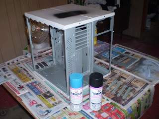
CASE: My custom made double sized monstrosity. (pic)
This is a computer case I had built from two old computer cases. A recycled case not only saves in the wallet, but also saves the environment.
Some key features of this custom case:
-Eco-Friendly: These cases would have most likely been dumped into a landfill. They are 100% recycled cases.
-Large: Right now I have it fitting comfortably a full sized ATX motherboard, with video card, optical drive, multiple hard drives, fanbus, power supply, radiator, water pump, fans, and 8 UV cathode lights. I plan to house multiple radiators and more fans to help better cool the new system!
-Portability: Well, it is large, so it actually is not that portable; But I have helped remedy this problem by adding rubber wheels under the case, as well as two large carrying handles. Coming in and out of my apartment I wheel this baby down the hallway with my monitor, keyboard, mouse, and headset on top of the case; one trip!
-Water-Cooling: I already have a water cooling setup in this case. One radiator and pump has been cut out and installed, two T-lines have been installed with a fill-port and "drain"-port. This will reduce build time significantly!
-Lighting: Eight 12 inch UV Cathodes brightly light the inside of this case. UV reactive dyes and water additives in the cooling system glow nicely with the help of these cathodes. Various internal connectors, Sata cables, and the PCB of the motherboard and Video card tend to add to the cool factor of any system.
WATERCOOLING: Currently running Danger-Den's 2x120 Radiator, Liang D5 Pump, 2x Danger Den Fill ports, 2x UV reactive Y-adapters (I prefer these to actual T-adapters for doing T-lines for fill/drain-ports). I have additional UV Dye and water additives on hand to mix a new batch of coolant. Additional Parts will be required and outlined further down.
FANS: Nexus Fan Controller and many Scythe Slip Stream (Kaze-Jyuni) 120mm Fans of various speeds. I have used many of these fans in my current and past builds. They provide awesome noise to airflow ratios (more air moves with less noise!). I like to control the higher (1800+) rpm fans with a fan bus; I like to have the fans turned down while not gaming to reduce noise so I can do other things (like sleeping!). These fans will be used to cool the voltage regulators, as well as be attached to the multiple radiators used inside the system.
OPTICAL DRIVE: Samsung Dual Layer DVD Burner SATA Black Drive. Not much is needed to be said here. It will burn and play DVD's and CD's.
HARDDRIVES: Extra storage for this project will be nice. I currently have four 500gb hard drives at my disposal to use (these include three Seagate SATAII 32mb drives, and one Western Digital Black Edition 32mb drive).
OPERATING SYSTEM: Windows 7 Professional (64-bit) edition. This is a legitimate copy purchased through Microsoft's Student Deals. This will be the OS of choice for this project, as it has added support for SSD hard drives, and will take full advantage to all 4gb of the system's ram.
MONITOR: I currently own a 21.5 inch Samsung SyncMaster 2233 monitor. It has an amazing 1080P native resolution, 50,000:1 dynamic contrast ratio, and a 5ms refresh rate; this is an awesome gaming monitor.
MOUSEPAD: Currently using a Razer Mantis Control mouse pad with my Razer mouse. This should couple with the Razer Death Adder mouse very well.
HEADSET: Plantronics .Audio 750 DSP head set. This headset was a great value; the voice and sound quality from this set is amazing, and was easy on the wallet.
Additional Hardware to be purchased:
WATERCOOLING: I would need a water block designed for the Nvidia GTX260 video card, so both the GPU and RAM will receive the best possible cooling. I will also need a CPU water block to fit the LGA1156 socket. I would also like to add one additional radiator to the setup. I would like to have a radiator added right before each water block, to ensure that coolant reaches the lowest temperature when it is delivered to the most vital components of the computer. Extra Tubing and hose clamps will be purchased from the local hardware store as needed.
CASEMODDING: Black and red spray paint, black vinyl dye, and clear plexi-glass. To add further "wow" and "cool" factors to the build, I would like the exterior of the computer to be a nice solid black color, as well as the inside being a blood red color. Plexi-glass windows will cut out into the sides of the case to show off the components, and red interior.
MOUNTING: There are currently only three 3.5 inch bays and three 5.25 inch bays. One 5.25 inch bay will hold the optical drive, one 3.5 inch bay will hold the fan bus. Two 5.25 bays will need mounting adapters to hold two 3.5 inch hard drives, and two 3.5 inch bays will hold two 3.5 inch hard drives. An additional 2.5 inch mounting adapter will be needed for the Samsung SSD hard drive; I plan to mod and fabricate a mount, so the hard drive can be clearly visible from the outside through the plexi-glass window.
PAINT: Going to Lan Parties sponsored by ASUS ROG, I would like to further honor the ROG way by painting my case to match the community. I plan to dye the front panel black, and paint all the side panels and exterior pieces black. I would also like to paint the inside of the case red.
Work to be done (in no particular order):
-Install two extra radiators into the case.
-fabricate front panel to hold radiator
-Paint interior and exterior of case with separate colors.
-Cut side panels, and Install plexi-glass windows.
-Mod/fabricate 2.5 inch hard drive bay, to have hard drive visible from plexi-glass windows.
-Install all components into case.
-Dry fit water cooling loop, and later Leak test loop with hardware removed.
-Test over clocking abilities of each components (CPU, RAM, GPU), and come up with the most ideal set of settings for gaming.
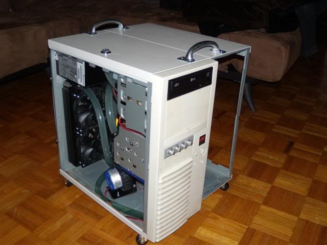
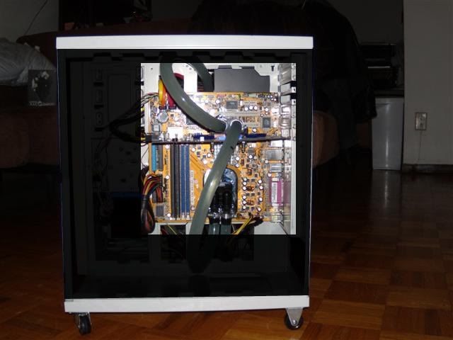
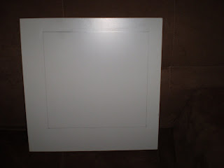
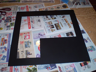
This is my case as-is right now with the side panels removed. I have side panels (not shown) that currently have no moddification to them I plan on cutting plexi-glass windows into them.
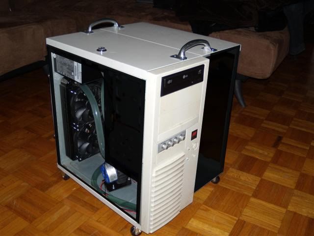
Black panels in this picture shows how the window will look once I mod the side panels. I will also be painting the outside fo the case black.
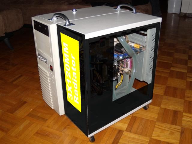
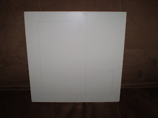
Black panels in this picture shows how the window will look once I mod the side panels. I will also be painting the outside of the case black. You can also see where the additional radiator that will be installed, represented by the yellow panel. The front will need a panel fabricated and modded to hold the radiator.
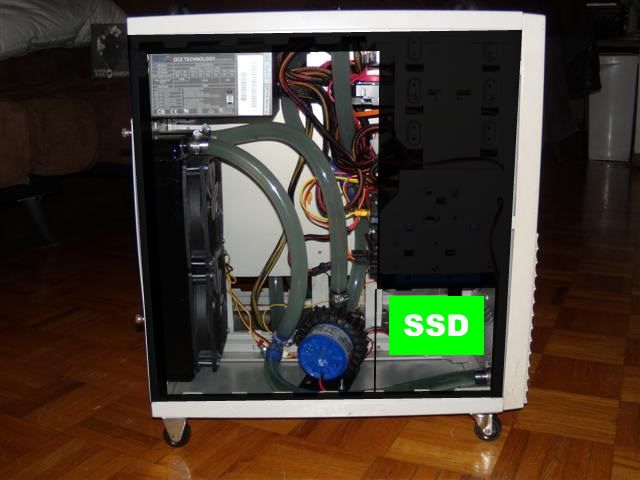 This is the expected side view of the finished build. the interior of the case will also be painted red. I will also have the SSD being displayed where the green panel is shown.
This is expected side view of the finished build. I plan to hide the cabling and the second radiator as best as possible.
This is a rough diagram of the water cooling loop will work
There will be a 2x120mm radiator before each water block. This should help cool the CPU and GPU even better! There is also a T-line fillport right before the inlet of the pump, this will eliminate the need of having a reservoir. There is also T-line after the pump, to help drain the loop.
Why an ASUS "Xtreme" System Setup?
What Would I do?
My Xtreme System would need to push the limits of its given hardware to provide the best gaming experience; while keep a low audible noise level.
Why gaming? Why not? With the recent release of the Nintendo Wii, and games such as Rock Band, Guitar Hero and World of Warcraft, the gaming community has grown to be much more widely acceptable in most social circles. Gaming is no longer "nerdy" or "for geeks only"; it is becoming one of the most favorable past times by children, teens, young adults, adults, and seniors!
Why do I want low noise levels? Again, why not? Who wants to hear loud buzzing fans these days? If I liked the sound of jumbo jets taking off all day, I would hang around airports more often; But I don't. I also like it quiet while I sleep; so when the occasion of virus scanning or hard drive defragmentation needs to be done I generally run them while I sleep to minimize the impact on my gaming schedule.
My Project goals:
-I would need to design and build a water cooling loop to keep vital components at or below the recommended maximum operating temperature. CPU and GPU would need to be liquid cooled at minimum. Other components (chipset, voltage regulators, ram, hard drives, etc..) will be cooling conventionally with heatsinks and/or fans.
-To custom build a case to house the computer components and water cooling system. The water cooling system would need to be housed completely internally; no component (including fans, pumps, and radiators) will be outside of the case (normal external peripherals are not be part of this constraint).
How will ASUS's Xtreme Design Motherboard features will aid in my project?
I have no experience over clocking any of the new LGA1156 cpu's. The new Turbo V will make adjusting cpu voltages, frequencies, and multipliers much easier and much quicker by staying within windows and not needing restart after every change.
Couple the Turbo V feature with ASUS’ Turbo key, I will also be able to save power. I will be able to turn down the clock speeds back down to stock, to help save and conserve power.
The Xtreme Phase design is not only more power efficient, but also produces less heat. Heat will be the number one unwanted by-product of overclocking. Having a motherboard with already built in features for reducing heat is one less thing I need to worry about when trying to push my system to its limits.
What I already have:
CASE: My custom made double sized monstrosity. (pic)
This is a computer case I had built from two old computer cases. A recycled case not only saves in the wallet, but also saves the environment.
Some key features of this custom case:
-Eco-Friendly: These cases would have most likely been dumped into a landfill. They are 100% recycled cases.
-Large: Right now I have it fitting comfortably a full sized ATX motherboard, with video card, optical drive, multiple hard drives, fanbus, power supply, radiator, water pump, fans, and 8 UV cathode lights. I plan to house multiple radiators and more fans to help better cool the new system!
-Portability: Well, it is large, so it actually is not that portable; But I have helped remedy this problem by adding rubber wheels under the case, as well as two large carrying handles. Coming in and out of my apartment I wheel this baby down the hallway with my monitor, keyboard, mouse, and headset on top of the case; one trip!
-Water-Cooling: I already have a water cooling setup in this case. One radiator and pump has been cut out and installed, two T-lines have been installed with a fill-port and "drain"-port. This will reduce build time significantly!
-Lighting: Eight 12 inch UV Cathodes brightly light the inside of this case. UV reactive dyes and water additives in the cooling system glow nicely with the help of these cathodes. Various internal connectors, Sata cables, and the PCB of the motherboard and Video card tend to add to the cool factor of any system.
WATERCOOLING: Currently running Danger-Den's 2x120 Radiator, Liang D5 Pump, 2x Danger Den Fill ports, 2x UV reactive Y-adapters (I prefer these to actual T-adapters for doing T-lines for fill/drain-ports). I have additional UV Dye and water additives on hand to mix a new batch of coolant. Additional Parts will be required and outlined further down.
FANS: Nexus Fan Controller and many Scythe Slip Stream (Kaze-Jyuni) 120mm Fans of various speeds. I have used many of these fans in my current and past builds. They provide awesome noise to airflow ratios (more air moves with less noise!). I like to control the higher (1800+) rpm fans with a fan bus; I like to have the fans turned down while not gaming to reduce noise so I can do other things (like sleeping!). These fans will be used to cool the voltage regulators, as well as be attached to the multiple radiators used inside the system.
OPTICAL DRIVE: Samsung Dual Layer DVD Burner SATA Black Drive. Not much is needed to be said here. It will burn and play DVD's and CD's.
HARDDRIVES: Extra storage for this project will be nice. I currently have four 500gb hard drives at my disposal to use (these include three Seagate SATAII 32mb drives, and one Western Digital Black Edition 32mb drive).
OPERATING SYSTEM: Windows 7 Professional (64-bit) edition. This is a legitimate copy purchased through Microsoft's Student Deals. This will be the OS of choice for this project, as it has added support for SSD hard drives, and will take full advantage to all 4gb of the system's ram.
MONITOR: I currently own a 21.5 inch Samsung SyncMaster 2233 monitor. It has an amazing 1080P native resolution, 50,000:1 dynamic contrast ratio, and a 5ms refresh rate; this is an awesome gaming monitor.
MOUSEPAD: Currently using a Razer Mantis Control mouse pad with my Razer mouse. This should couple with the Razer Death Adder mouse very well.
HEADSET: Plantronics .Audio 750 DSP head set. This headset was a great value; the voice and sound quality from this set is amazing, and was easy on the wallet.
Additional Hardware to be purchased:
WATERCOOLING: I would need a water block designed for the Nvidia GTX260 video card, so both the GPU and RAM will receive the best possible cooling. I will also need a CPU water block to fit the LGA1156 socket. I would also like to add one additional radiator to the setup. I would like to have a radiator added right before each water block, to ensure that coolant reaches the lowest temperature when it is delivered to the most vital components of the computer. Extra Tubing and hose clamps will be purchased from the local hardware store as needed.
CASEMODDING: Black and red spray paint, black vinyl dye, and clear plexi-glass. To add further "wow" and "cool" factors to the build, I would like the exterior of the computer to be a nice solid black color, as well as the inside being a blood red color. Plexi-glass windows will cut out into the sides of the case to show off the components, and red interior.
MOUNTING: There are currently only three 3.5 inch bays and three 5.25 inch bays. One 5.25 inch bay will hold the optical drive, one 3.5 inch bay will hold the fan bus. Two 5.25 bays will need mounting adapters to hold two 3.5 inch hard drives, and two 3.5 inch bays will hold two 3.5 inch hard drives. An additional 2.5 inch mounting adapter will be needed for the Samsung SSD hard drive; I plan to mod and fabricate a mount, so the hard drive can be clearly visible from the outside through the plexi-glass window.
PAINT: Going to Lan Parties sponsored by ASUS ROG, I would like to further honor the ROG way by painting my case to match the community. I plan to dye the front panel black, and paint all the side panels and exterior pieces black. I would also like to paint the inside of the case red.
Work to be done (in no particular order):
-Install two extra radiators into the case.
-fabricate front panel to hold radiator
-Paint interior and exterior of case with separate colors.
-Cut side panels, and Install plexi-glass windows.
-Mod/fabricate 2.5 inch hard drive bay, to have hard drive visible from plexi-glass windows.
-Install all components into case.
-Dry fit water cooling loop, and later Leak test loop with hardware removed.
-Test over clocking abilities of each components (CPU, RAM, GPU), and come up with the most ideal set of settings for gaming.
This is my case as-is right now with the side panels removed. I have side panels (not shown) that currently have no moddification to them I plan on cutting plexi-glass windows into them.
Black panels in this picture shows how the window will look once I mod the side panels. I will also be painting the outside fo the case black.
Black panels in this picture shows how the window will look once I mod the side panels. I will also be painting the outside of the case black. You can also see where the additional radiator that will be installed, represented by the yellow panel. The front will need a panel fabricated and modded to hold the radiator.
This is the expected side view of the finished build. the interior of the case will also be painted red. I will also have the SSD being displayed where the green panel is shown.This is expected side view of the finished build. I plan to hide the cabling and the second radiator as best as possible.
This is a rough diagram of the water cooling loop will work
There will be a 2x120mm radiator before each water block. This should help cool the CPU and GPU even better! There is also a T-line fillport right before the inlet of the pump, this will eliminate the need of having a reservoir. There is also T-line after the pump, to help drain the loop.
Changes and Clarifications
So, as I had mentioned in an earlier post I have minor changes to my build that I had identified when I began to further plan the project.
The biggest change is the additional radiator I am using. I originally posted in my entry that I was going to use two 2x120mm radiators. Actually if you look closer at the original entry, on one of my mock up pictures I had made, I had labeled the radiator a the front of the case would be a 3x120mm. Apparently my subconscious is psychic and saw intot he future that I would indeed be using a 3x120mm radiator...
With that being said, I will be actually using my original 2x120mm radiator, and an additional 3x120mm radiator. Reason for changing: when I went to go order additional water cooling parts, the Fesser One TFC Triple Xchanger (3x120mm) radiator was onsale. It was still cheaper for a Swiftech 2x120mm radiator, or even the Fesser One TFC Dual Xchanger (2x120mm) radiator the 3x120mm radiator should be able to transfer heat much better.
Next, Interior case color will change from being red, to blue. Reason: ASUS P7P55 motherboards use a nice blue theme. Why fight it? there really is no way of changing it.
Now with going with a blue theme, I will be getting blue UV reactive tubing, opposed to using clear tubing and coolant dye.
I will also be trying to change the color theme of the Antec Power supply from yellow to blue. I will see once I get the power supply what will all be involved. All I can tell currently, is that I will be covering over the yellow on the power supply with blue.
There will probably be more minor changes in the future. I imagine there will be road blocks during my build, and I will need to adjust some of my planning to overcome some challenges.
Parts Order
So my parts order for water cooling products had came in today...
I had began to research and order the water cooling products as soon as I was announced as a stage one winner. It sometimes takes a bit of time tracking down water blocks and specific water cooling products, so I wanted to order the parts as soon as possible.
There were some issues trying to find the correct water blocks for the build. At first I knew there would be few choices for lga1156 socket coolers. Even if I were to use aftermarket air coolers, there are very few choices for models and manufacturers. Water blocks, even tougher.
The mounting holes for lga1156 coolers is the primarily the problem. The hole spacing is smaller than that of a lga1366 socket, but larger than that of a lga775. What I did find, was EK water blocks that were made for lga775 and lga1366 sockets used slots rather than holes for their mounting holes.
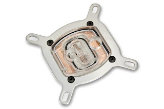
As you can see, slotted holes!
So like you can see, since the lga1156 mounting holes are between the other two sockets, this will work with a lga1156!
Now, what I did not count on, was not being able to find a full cover gtx260 water block. There are couple versions of the gtx260 gpu; one of the biggest differences is the manufacturing process technology, 55nm vs 65nm. I'm not a computer hardware engineer, but the key difference between the two manufacturing processes, is how tight they make the tiny capacitors and compact the tiny circuits. Another side note, smaller the better.
Anyways, what it means for finding a gpu water block, is that nvidia change the mounting holes and pcb design for their video card when the later introduced the 55nm gpu. With that, it seems not many manufacturers who normally produce full cover water blocks, actually made any water blocks for the gtx260.
I did find out that the ASUS gtx260 Glaciator video card is a 55nm gpu.
The other kick in the pants, is that there is apparently a few pcb design layout differences for the 55nm gtx260.
I did find an EK full cover gtx260 water block for 55nm video card. Unfortunately no one has seemed to try this with the ASUS Gladiator gtx260, but it is the closest thing I have found.
Now, the next hurdle; finding a place to order EK water blocks, and who have in stock. EK water blocks is produced in Slovenia, a European country. EK is kinda tough to find within north america, and if you do find it, they are pretty expensive.
I did find a company within Canada. DazMode.com has a pretty good selection of EK waterblocks, IN STOCK! I ended up emailing Dazmin himself just to confirm some things; he replied back to my message within an hour, not only that but I emailed him late night around 10PM his time. That I was impressed with. We emailed back and forth, and I ended up ordering parts that night before bed (I am part night hawk).
I ended up ordering the EK-FC260 Nickle\plexi full cover water block (this was open box, and was about 60 dollars off!), EK-Supreme-Plexi cpu water block, 12ft of Fesser One UV Blue tubing, 6 Fesser One 1/2inch g1/4 barbs, and lastly a Fesser One TFC XChanger triple radiator.
I was originally looking at only getting a dual radiator, however DazMode.com had the XChanger radiators on special, I ended up getting the triple radiator for only $99.99!
I also wanted to make 250 dollars to take advantage of the free shipping offer from the website, which I did.
As for order speed, I ordered the parts about 2AM November 18th, and received the parts today on the 23rd.
I have not opened the box yet, I am not even at home currently. I had the package sent to my mother's house (since she is at home all day) so I actually have to go over and pick that up later today.
[/img]
I had began to research and order the water cooling products as soon as I was announced as a stage one winner. It sometimes takes a bit of time tracking down water blocks and specific water cooling products, so I wanted to order the parts as soon as possible.
There were some issues trying to find the correct water blocks for the build. At first I knew there would be few choices for lga1156 socket coolers. Even if I were to use aftermarket air coolers, there are very few choices for models and manufacturers. Water blocks, even tougher.
The mounting holes for lga1156 coolers is the primarily the problem. The hole spacing is smaller than that of a lga1366 socket, but larger than that of a lga775. What I did find, was EK water blocks that were made for lga775 and lga1366 sockets used slots rather than holes for their mounting holes.
As you can see, slotted holes!
So like you can see, since the lga1156 mounting holes are between the other two sockets, this will work with a lga1156!
Now, what I did not count on, was not being able to find a full cover gtx260 water block. There are couple versions of the gtx260 gpu; one of the biggest differences is the manufacturing process technology, 55nm vs 65nm. I'm not a computer hardware engineer, but the key difference between the two manufacturing processes, is how tight they make the tiny capacitors and compact the tiny circuits. Another side note, smaller the better.
Anyways, what it means for finding a gpu water block, is that nvidia change the mounting holes and pcb design for their video card when the later introduced the 55nm gpu. With that, it seems not many manufacturers who normally produce full cover water blocks, actually made any water blocks for the gtx260.
I did find out that the ASUS gtx260 Glaciator video card is a 55nm gpu.
The other kick in the pants, is that there is apparently a few pcb design layout differences for the 55nm gtx260.
I did find an EK full cover gtx260 water block for 55nm video card. Unfortunately no one has seemed to try this with the ASUS Gladiator gtx260, but it is the closest thing I have found.
Now, the next hurdle; finding a place to order EK water blocks, and who have in stock. EK water blocks is produced in Slovenia, a European country. EK is kinda tough to find within north america, and if you do find it, they are pretty expensive.
I did find a company within Canada. DazMode.com has a pretty good selection of EK waterblocks, IN STOCK! I ended up emailing Dazmin himself just to confirm some things; he replied back to my message within an hour, not only that but I emailed him late night around 10PM his time. That I was impressed with. We emailed back and forth, and I ended up ordering parts that night before bed (I am part night hawk).
I ended up ordering the EK-FC260 Nickle\plexi full cover water block (this was open box, and was about 60 dollars off!), EK-Supreme-Plexi cpu water block, 12ft of Fesser One UV Blue tubing, 6 Fesser One 1/2inch g1/4 barbs, and lastly a Fesser One TFC XChanger triple radiator.
I was originally looking at only getting a dual radiator, however DazMode.com had the XChanger radiators on special, I ended up getting the triple radiator for only $99.99!
I also wanted to make 250 dollars to take advantage of the free shipping offer from the website, which I did.
As for order speed, I ordered the parts about 2AM November 18th, and received the parts today on the 23rd.
I have not opened the box yet, I am not even at home currently. I had the package sent to my mother's house (since she is at home all day) so I actually have to go over and pick that up later today.
[/img]
Box Opening!
So Like I said, I would post all the pictures and video at a later date. I had a bit of a hard time getting pictures off my camera, since I took apart my main computer for the build last sunday. Slight oversight on my part, but I do have other comptuers to use.
I apologize, there is no video as of now, since I lost my firewire cable
I will purchase a new one tonight, and see if I can upload the video to you tube by the end of this week.
For now pictures!
Thank You ASUS and Sponsors!

This is a mouse pad, there was also a
Republican of Gamers T-Shirt I forgot to get a picture of
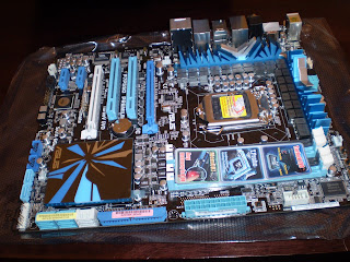
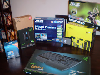
Here is the ASUS P7P55D Premium Motherboard
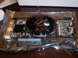
ASUS ENGTX260 Glaciator video card (896MB)
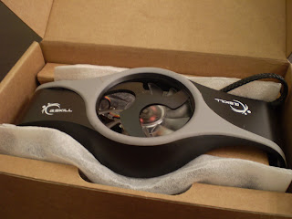
G.Skills 2x2gb TDS Dual Channel Memory kit (2133mhz)
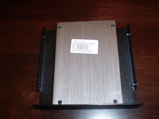
Samsung 128gb SSD HDD w/ 2.5" to 3.5" adapter
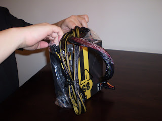
Antec Quattro 850w Modular PSU
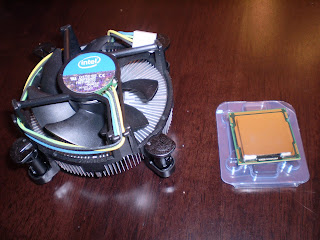
Intel LGA1156 Core i7 860 CPU
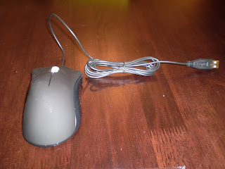
Razer Death Adder Mouse
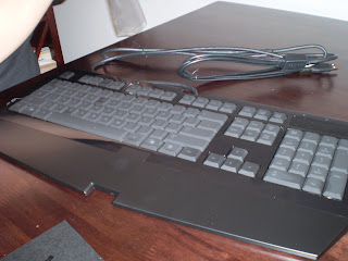
Razer Lycosa Keyboard
So some after thoughts of unboxing everything. These are just some after thougths I had that I would like to share.
Razer does a very good job making their packaging visually pleasing. There was not much in the way of wasted packing materials, and everything seemed to have a purpose of protecting and presenting the product.
The Antec power supply had the best packing. They seemed to use the absolute minimum amount of packaging, but I am 100% confident it arrived in perfect working condition. More things need to be packed this well and minimally.
I apologize, there is no video as of now, since I lost my firewire cable
I will purchase a new one tonight, and see if I can upload the video to you tube by the end of this week.
For now pictures!
Thank You ASUS and Sponsors!
This is a mouse pad, there was also a
Republican of Gamers T-Shirt I forgot to get a picture of
Here is the ASUS P7P55D Premium Motherboard
ASUS ENGTX260 Glaciator video card (896MB)
G.Skills 2x2gb TDS Dual Channel Memory kit (2133mhz)
Samsung 128gb SSD HDD w/ 2.5" to 3.5" adapter
Antec Quattro 850w Modular PSU
Intel LGA1156 Core i7 860 CPU
Razer Death Adder Mouse
Razer Lycosa Keyboard
So some after thoughts of unboxing everything. These are just some after thougths I had that I would like to share.
Razer does a very good job making their packaging visually pleasing. There was not much in the way of wasted packing materials, and everything seemed to have a purpose of protecting and presenting the product.
The Antec power supply had the best packing. They seemed to use the absolute minimum amount of packaging, but I am 100% confident it arrived in perfect working condition. More things need to be packed this well and minimally.
Unboxing water coolign parts
So, also on Monday I recieved the water cooling parts I ordered. I also took pictures of the unboxing...
Here they are!
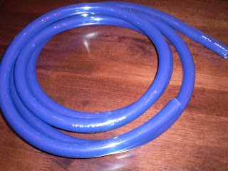
12' of Fesser One UV 1/2 I.D. Tubing
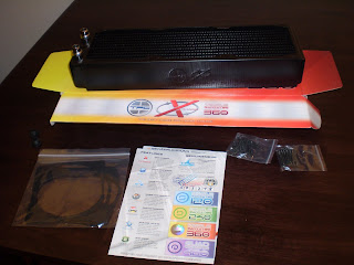
Fesser One TFC Xchanger Triple Radiator
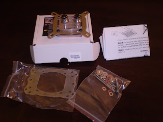
EK-Supreme Plexi CPU water block
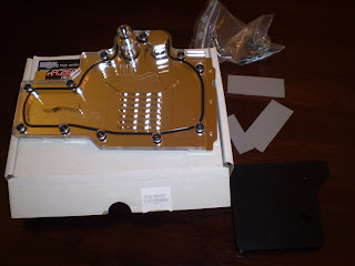
EK-FC260 GPU water block
A Gift from DazMode.com, Thank you!
Here they are!
12' of Fesser One UV 1/2 I.D. Tubing
Fesser One TFC Xchanger Triple Radiator
EK-Supreme Plexi CPU water block
EK-FC260 GPU water block
A Gift from DazMode.com, Thank you!
POST Test and Some Bench Test
So, last night I did a POST Test with the goodies I received. I will be voiding warranties here, (no doubts about that) so I may aswell make sure everything powers one correctly before going much further.
I'll let the captions under the pictures guide you.
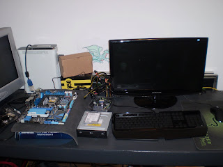
Laying out the goods
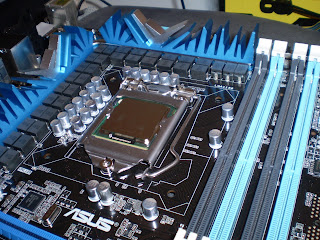
Installing the CPU
I did install the heatsink, but forgot to get a photo of it
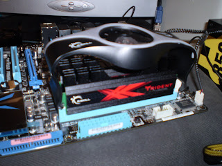
Ram and Ram Cooler installed

Video Card Installed
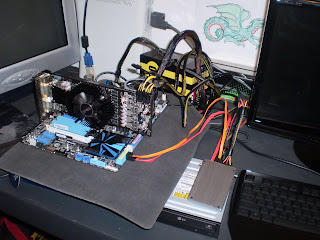
Hooked up the drives, power, keyboard and mouse
Now for the POST test to begin!
Thanks to the handy power and reset button, I didn't even need a screw driver to turn it on. One of the many great features of this mother board!
So POST Success! took me a few tries to get at the BIOS setup. I wanted to make sure nothing was setup too terribly wrong, and wanted to make sure things were being detected properly.
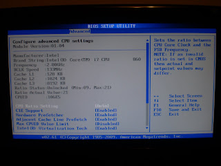
CPU detected properly!
There was a few things I changed.
First was the boot order, I personally like Optical drive -> Hard Drive -> nothing. There was an option for USB devices, but I have had that screw up with certain USB devices in the past. Also I would boot from a USB device maybe once or twice ever, so I'll just go to the boot menu if need be.
Second thing to change was turning off express gate. It is a cool function and all, but when I'm testing and planning on installing windows it can be turned off for now. I will probably play with it later.
Next was the ram. Now, this was kinda screwy, as 2133mhz was not on the lsit of available speed, the quickest ram allowed was 1600mhz. That's nearly 600mhz slower than what the ram was advertised to run. Now I enabled D.O.C.P. as the "Ai Overclock Tuner", which gave me the option for 2133mhz. However after I set the ram at this speed, the motherboard would post, but get stuck at a screen giving me an error that one of the drive controllers could not detect a drive attached. I am pretty sure I need to play with adding voltage to the Dram to make it stable, but for now I decided to just keep it at 1600mhz.
After getting that all straightened out, I decided to install Windows 7 Professional (64-bit) onto the solid state drive. One of the nice things about Windows 7 is it takes about a half hour at most to install on conventional drives. With the SSD, I setup all the settings it needed, and went and made myself a snack (sandwich, had some pudding, and other goodies) as it started installing files. not even 10 minutes later I'm back and it's done; Nice!
Time to check it out. I cracked open the device manager, and was pleasantly surprised everything was detected and had drivers installed. Who knows if anything is out of date, or not functioning, but at least I'm not needing to find drivers for the NIC, and having to try to find more drivers off the internet.
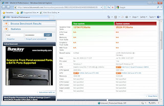
Lets try the Windows Experience Index. I don't usually hold any sort hope that this is an accurate measure of the computer, but I was interested to see what it had to say.
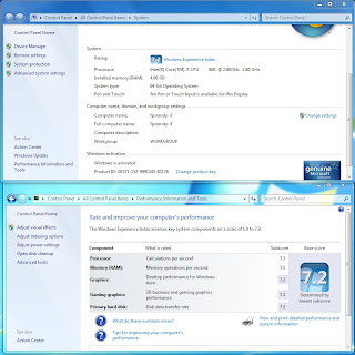
You will probably have to goto the blog to see the details
You can probably see the overall score of 7.2
Not too shabby in my opinion. I was secretly hoping for this to score over 8, but 7.2 is about 50% higher than my computer just previous to this. Apparently the graphics card and hard drive is holding this back. Not much I can do about the hard drive, but once the water cooling loop is installed, I'll see what I can do about the graphics score, and the cpu score. The memory score should also increase once I get the ram up to its rated speed aswell.
Now for some Futuremark Tests. I ended up getting PCMark05 and 3DMark05. Why? because they are free, and one of the forums I lurk on uses it them. Once I have the liquid cooling running, I will benchmark with some newer tests.
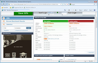
3DMark05: 23,000pts (Even)
PCMark05: 12,794pts
Well, these look promising. Again, miles better than my previous setup. Remember, this was absolutely no tweaking, no windows updates, stock speeds (exception to the ram being under clocked), and stock cooling. Wait in a week or two to see the updated scores once everything is setup.
Check the blog for better resolution pictures! http://www.xtremebuild.info
I'll let the captions under the pictures guide you.
Laying out the goods
Installing the CPU
I did install the heatsink, but forgot to get a photo of it
Ram and Ram Cooler installed
Video Card Installed
Hooked up the drives, power, keyboard and mouse
Now for the POST test to begin!
Thanks to the handy power and reset button, I didn't even need a screw driver to turn it on. One of the many great features of this mother board!
So POST Success! took me a few tries to get at the BIOS setup. I wanted to make sure nothing was setup too terribly wrong, and wanted to make sure things were being detected properly.
CPU detected properly!
There was a few things I changed.
First was the boot order, I personally like Optical drive -> Hard Drive -> nothing. There was an option for USB devices, but I have had that screw up with certain USB devices in the past. Also I would boot from a USB device maybe once or twice ever, so I'll just go to the boot menu if need be.
Second thing to change was turning off express gate. It is a cool function and all, but when I'm testing and planning on installing windows it can be turned off for now. I will probably play with it later.
Next was the ram. Now, this was kinda screwy, as 2133mhz was not on the lsit of available speed, the quickest ram allowed was 1600mhz. That's nearly 600mhz slower than what the ram was advertised to run. Now I enabled D.O.C.P. as the "Ai Overclock Tuner", which gave me the option for 2133mhz. However after I set the ram at this speed, the motherboard would post, but get stuck at a screen giving me an error that one of the drive controllers could not detect a drive attached. I am pretty sure I need to play with adding voltage to the Dram to make it stable, but for now I decided to just keep it at 1600mhz.
After getting that all straightened out, I decided to install Windows 7 Professional (64-bit) onto the solid state drive. One of the nice things about Windows 7 is it takes about a half hour at most to install on conventional drives. With the SSD, I setup all the settings it needed, and went and made myself a snack (sandwich, had some pudding, and other goodies) as it started installing files. not even 10 minutes later I'm back and it's done; Nice!
Time to check it out. I cracked open the device manager, and was pleasantly surprised everything was detected and had drivers installed. Who knows if anything is out of date, or not functioning, but at least I'm not needing to find drivers for the NIC, and having to try to find more drivers off the internet.
Lets try the Windows Experience Index. I don't usually hold any sort hope that this is an accurate measure of the computer, but I was interested to see what it had to say.
You will probably have to goto the blog to see the details
You can probably see the overall score of 7.2
Not too shabby in my opinion. I was secretly hoping for this to score over 8, but 7.2 is about 50% higher than my computer just previous to this. Apparently the graphics card and hard drive is holding this back. Not much I can do about the hard drive, but once the water cooling loop is installed, I'll see what I can do about the graphics score, and the cpu score. The memory score should also increase once I get the ram up to its rated speed aswell.
Now for some Futuremark Tests. I ended up getting PCMark05 and 3DMark05. Why? because they are free, and one of the forums I lurk on uses it them. Once I have the liquid cooling running, I will benchmark with some newer tests.
3DMark05: 23,000pts (Even)
PCMark05: 12,794pts
Well, these look promising. Again, miles better than my previous setup. Remember, this was absolutely no tweaking, no windows updates, stock speeds (exception to the ram being under clocked), and stock cooling. Wait in a week or two to see the updated scores once everything is setup.
Check the blog for better resolution pictures! http://www.xtremebuild.info
Wow--there's a way to start off at SPCR 
Good to see manufacturers getting interested in quiet parts--it's a lot easier to build something reasonably quiet than even when I joined a couple years ago.
What kind of fans are going on the radiators? And where are they getting mounted? Was there any consideration to the Zalman Reserator setup? That seems to be a good one for water systems that are especially interested in noise.
Welcome to SPCR!
I apologize for the late reply.
Yes, so far my experience here has be quite awesome 
I have been using 120mm Scythe fans. Specifically Slip Stream Jyuni 1800rpm. The 1800rpm fans are slightly audible; however I think I forgot to mention that I own a fan controller for them that I will be using to set them down to a lower speed so they will not make any noise. I like these fans for the price and performance of the fans. I can get the fans for about 10 dollars CAD and claim to push 110cfm at 37dba. Again, not quiet when they are set to go at full, but at least I have the adjustment for when the weather gets warmer and when I start gaming.
The Fans will be primarily mounted on the radiators. My last computer I had an extra fan mounted onto the top of the gou water block to help cool the ram (they had passive ram sinks attached to them). I will be using a full cover block on this build, so I will not need that extra fan.
I am debating whether I will be using the G.Skills memory cooler that came with the memory or another Scythe fan. If I do change fans for the memory it will be the same type of Scythe, but with a lower rpm version (most likely the 800rpm fan, since I have a few extra in my parts bin.
I had looked at using the Zalman Reserator in the past. I am not too keen on having it outside separate from the computer case as it would be a pain to transport the computer to LAN parties. The other thing I had researched that they did not seem to cool the system as well as most radiators. Having everything contained inside the case is something I really like, which is why I had built the case so large.
Yes, so far my experience here has be quite awesome
I have been using 120mm Scythe fans. Specifically Slip Stream Jyuni 1800rpm. The 1800rpm fans are slightly audible; however I think I forgot to mention that I own a fan controller for them that I will be using to set them down to a lower speed so they will not make any noise. I like these fans for the price and performance of the fans. I can get the fans for about 10 dollars CAD and claim to push 110cfm at 37dba. Again, not quiet when they are set to go at full, but at least I have the adjustment for when the weather gets warmer and when I start gaming.
The Fans will be primarily mounted on the radiators. My last computer I had an extra fan mounted onto the top of the gou water block to help cool the ram (they had passive ram sinks attached to them). I will be using a full cover block on this build, so I will not need that extra fan.
I am debating whether I will be using the G.Skills memory cooler that came with the memory or another Scythe fan. If I do change fans for the memory it will be the same type of Scythe, but with a lower rpm version (most likely the 800rpm fan, since I have a few extra in my parts bin.
I had looked at using the Zalman Reserator in the past. I am not too keen on having it outside separate from the computer case as it would be a pain to transport the computer to LAN parties. The other thing I had researched that they did not seem to cool the system as well as most radiators. Having everything contained inside the case is something I really like, which is why I had built the case so large.
My apologies for not keeping this up to date. I would like to blame college classes for taking away from my free time. I had three choices with what to do with my free time being: Homework, Project Build, or Project Blog. Since as you can see I have been slacking on the blog, I will present you with a huge update. This probably will not be dial up friendly, I warn you now...
Penciling out one of the side panels
Penciling side panel two
Using a hand nibbler I slowly start shaping the side panels into something prettier
I apologize now, I forgot my camera when I began working at my mothers (I use the basement to use power tools and spray painting) so I was forced to borrow her camera, which I have not yet taken the pictures from. I will update with more photos later of more of the prep work.
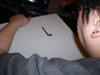
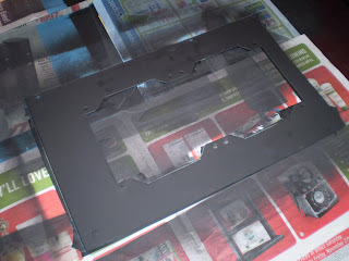
Ready for painting!
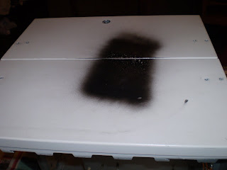
Incase you were wondering what was with the black rectangle on the top, this was me testing out the black paint.
I actually had painted the interior first with the blue paint. However this was the day I forgot my camera. I will post the interior paint pictures later.
Second day of painting I did remember my camera.I ended up taking awhile masking the case off with newspaper and masking tape, I was so pre-occupied I actually forgot to take photos of between masking it. Although showing you would be pretty boring anyways...
The outside being painted black. This is the bottom of the case. This is after coat two, of four. The flash does do the paint any justice
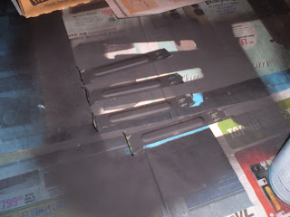
Painting the pci knock outs. The outsides are black, while the inside is blue
This is the back panel which holds the rear radiator.
So after doing the exterior, I removed all the masking I did. Unfortunately this pulled up a lot of the of the blue interior paint. I was very sad at this point. I normally do not prime my cases, but I usually use a different brand of paint (Rust-Oleum) which has never done this to me. Apparently even though Tremclad's rust paint that it would stick to bare metal without primer, it lies. Oh well, I had to make due, I ended up making a few extra coats in the interior to fix this, from far away it is impossible to tell. Up close with you eyes about 6 inches away you can see the different layers of paint.
All in all, the case overall looks pretty awesome in my opinion. I really like the blue and flat black. I had a lot of people questioning if glossy vs flat would look better, but I am pretty confident this was the better choice.
The paint is peeling off
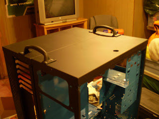
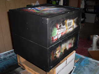
Case painting completed, with handles and wheel back on!
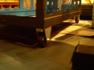
Shiny wheels
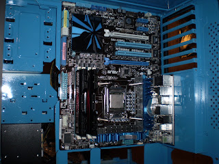
I installed the motherboard to see how the blues interacted with one another. My blue did not match, but really none of the blues on the motherboard did. Looks like win to me!
So there you have it, a long awaited update. The overall process of painting required three trips to my mother's house. Considering the only times I really had were weekends, this spanned over a week and a half. I also painted some of the side panels after I finished cutting the windows out. They are currently sitting in my living room waiting for me to cut some plexiglass to put on them. I will post the side panels once I finished them.
Edit: fix broken forum tags.
ALSO VISIT: http://xtremebuild.info for higher resolution pictures! also become a follower with your Google account!
Penciling out one of the side panels
Penciling side panel two
Using a hand nibbler I slowly start shaping the side panels into something prettier
I apologize now, I forgot my camera when I began working at my mothers (I use the basement to use power tools and spray painting) so I was forced to borrow her camera, which I have not yet taken the pictures from. I will update with more photos later of more of the prep work.
Ready for painting!
Incase you were wondering what was with the black rectangle on the top, this was me testing out the black paint.
I actually had painted the interior first with the blue paint. However this was the day I forgot my camera. I will post the interior paint pictures later.
Second day of painting I did remember my camera.I ended up taking awhile masking the case off with newspaper and masking tape, I was so pre-occupied I actually forgot to take photos of between masking it. Although showing you would be pretty boring anyways...
The outside being painted black. This is the bottom of the case. This is after coat two, of four. The flash does do the paint any justice
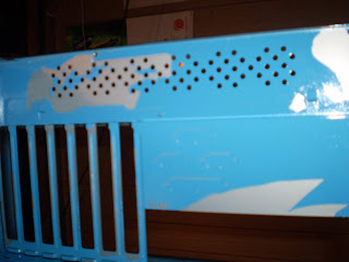
Painting the pci knock outs. The outsides are black, while the inside is blue
This is the back panel which holds the rear radiator.
So after doing the exterior, I removed all the masking I did. Unfortunately this pulled up a lot of the of the blue interior paint. I was very sad at this point. I normally do not prime my cases, but I usually use a different brand of paint (Rust-Oleum) which has never done this to me. Apparently even though Tremclad's rust paint that it would stick to bare metal without primer, it lies. Oh well, I had to make due, I ended up making a few extra coats in the interior to fix this, from far away it is impossible to tell. Up close with you eyes about 6 inches away you can see the different layers of paint.
All in all, the case overall looks pretty awesome in my opinion. I really like the blue and flat black. I had a lot of people questioning if glossy vs flat would look better, but I am pretty confident this was the better choice.
The paint is peeling off
Case painting completed, with handles and wheel back on!
Shiny wheels
I installed the motherboard to see how the blues interacted with one another. My blue did not match, but really none of the blues on the motherboard did. Looks like win to me!
So there you have it, a long awaited update. The overall process of painting required three trips to my mother's house. Considering the only times I really had were weekends, this spanned over a week and a half. I also painted some of the side panels after I finished cutting the windows out. They are currently sitting in my living room waiting for me to cut some plexiglass to put on them. I will post the side panels once I finished them.
Edit: fix broken forum tags.
ALSO VISIT: http://xtremebuild.info for higher resolution pictures! also become a follower with your Google account!
Last edited by fpsrandy on Mon Dec 14, 2009 9:47 pm, edited 1 time in total.
Also forgot to mention. View the blog I setup for higher resolution photos!
http://xtremebuild.info
http://xtremebuild.info
So now that the main chassis is painted, and the side panels are most of the way done, I began piecing the system together.
You may have noticed last post, on the last picture was the motherboard mounted inside the case, there were four long bolts coming through the cooler mounting holes. These bolts are part of the mounting hard ware to mount the waterblock for the liquid cooling system.
What I did not show was the video card and its mounted water block. Why? because the water block does not fit...
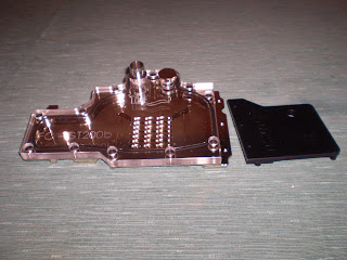
GPU water block
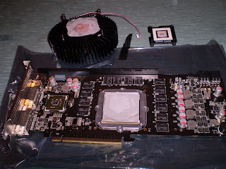
Stock coolers removed. I also had to remove an aluminum rail off the top of the card.
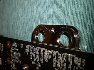
Capacitors in the way
As you can see there are two capacitors in the way. This may have stopped some people from moving forward, but not me. I pulled out my trusty rotary tool, and drill and began some of my own modification.
I began by removing the plexi top. I first cut the large finger of copper that was getting in the way of one of the capacitors (the one on the right, in the above photo). Then I drilled a pilot hole near one of holes that held the plexi top. I needed to be careful as I did not want to mess up a threaded hole that was holding the plexi top to the copper bottom. After increasing the size of the hole, by incrementally increasing the size of the drill bits, I used the rotary tool with a cut off blade to carefully complete the notch into the block.
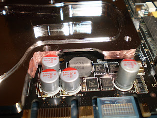
You can see there is now clearance for the capacitors.
Unfortunately I will not be able the nickle plate the bare copper areas
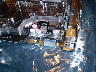
A new problem arose. for some reason the cooler was not flat while sitting on the card.
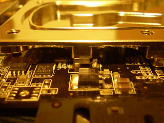
This appears to the be problem...
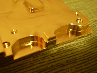
So that small raised bit of copper seems to be the problem.Nothing that a grinding tip on the rotary tool can't fix.
And we are clear!
Woo, we seem to now sit flat on the card.
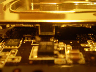
But, two problems quickly surface. I can get four of eight screws to line up. the other half seem to be about 3mm or 1/8 inch off! And it seems like there is even less room to get a fitting or plug onto the water block.
Looks like the card's PCB is a little larger...
After doing additional research, the ASUS Glaciator video card is NOT using the nVidia pcb reference design. It appears to be a slightly modified version, which is probably why there was clearance issues with the capacitors.
I see two options for water cooling: 1. New video card 2. New cooler
Well, I can't afford a new video card, and would like to use the one ASUS has given me. I also don't have time to have a new waterblock shipped to me soon enough that I would have time to leak test the cooling loop. So stock cooling it is for now
In the future, I will most likely be upgrading the video card. Generally for new builds (for gaming rigs), I budget almost 15-25% of my build (minus cooling) towards a graphics card, it seems to scale with the build overall without leaving a huge bottle neck. Considering that the cpu and ram are really kick ass, I would almost need a pair of 295's in sli to even come close to seeing a bottle neck on the cpu or ram.Of course when I do upgrade the video card, the new card will be water cooled (and I will research it much better).
This was a definitely my fault for not completely researching the Glaciator video card, and not checking earlier if the water block would fit. I was super chocked when I found out water cooling the video card would not be possible for this build
So... anyone want to buy a partly modified un-used water block for a 55nm gtx260?
You may have noticed last post, on the last picture was the motherboard mounted inside the case, there were four long bolts coming through the cooler mounting holes. These bolts are part of the mounting hard ware to mount the waterblock for the liquid cooling system.
What I did not show was the video card and its mounted water block. Why? because the water block does not fit...
GPU water block
Stock coolers removed. I also had to remove an aluminum rail off the top of the card.
Capacitors in the way
As you can see there are two capacitors in the way. This may have stopped some people from moving forward, but not me. I pulled out my trusty rotary tool, and drill and began some of my own modification.
I began by removing the plexi top. I first cut the large finger of copper that was getting in the way of one of the capacitors (the one on the right, in the above photo). Then I drilled a pilot hole near one of holes that held the plexi top. I needed to be careful as I did not want to mess up a threaded hole that was holding the plexi top to the copper bottom. After increasing the size of the hole, by incrementally increasing the size of the drill bits, I used the rotary tool with a cut off blade to carefully complete the notch into the block.
You can see there is now clearance for the capacitors.
Unfortunately I will not be able the nickle plate the bare copper areas
A new problem arose. for some reason the cooler was not flat while sitting on the card.
This appears to the be problem...
So that small raised bit of copper seems to be the problem.Nothing that a grinding tip on the rotary tool can't fix.
And we are clear!
Woo, we seem to now sit flat on the card.
But, two problems quickly surface. I can get four of eight screws to line up. the other half seem to be about 3mm or 1/8 inch off! And it seems like there is even less room to get a fitting or plug onto the water block.
Looks like the card's PCB is a little larger...
After doing additional research, the ASUS Glaciator video card is NOT using the nVidia pcb reference design. It appears to be a slightly modified version, which is probably why there was clearance issues with the capacitors.
I see two options for water cooling: 1. New video card 2. New cooler
Well, I can't afford a new video card, and would like to use the one ASUS has given me. I also don't have time to have a new waterblock shipped to me soon enough that I would have time to leak test the cooling loop. So stock cooling it is for now
In the future, I will most likely be upgrading the video card. Generally for new builds (for gaming rigs), I budget almost 15-25% of my build (minus cooling) towards a graphics card, it seems to scale with the build overall without leaving a huge bottle neck. Considering that the cpu and ram are really kick ass, I would almost need a pair of 295's in sli to even come close to seeing a bottle neck on the cpu or ram.Of course when I do upgrade the video card, the new card will be water cooled (and I will research it much better).
This was a definitely my fault for not completely researching the Glaciator video card, and not checking earlier if the water block would fit. I was super chocked when I found out water cooling the video card would not be possible for this build
So... anyone want to buy a partly modified un-used water block for a 55nm gtx260?
I post across many forums, unfortunately the ones I frequent were not hosting the competition.lm wrote:Well, my guess is this guy is only here because of the competition, and the choice of forum probably does not matter squat to him as long as he got his stuff. There won't probably be any posts by him to other threads ever. Nothing personal.psiu wrote:Wow--there's a way to start off at SPCR
I will not lie, the competition did bring me here. I chose this forum because I value silent computers, which by the title of this website I believed I could share a common interest with the community.
More posts will frequent once in the upcoming new year, after the competition and holidays are over. Spare time has been non-existent for me for the past few weeks; school, work, girlfriend, and competition barely leaves enough time in the day to cruise the internet.
Being in the future, I have to agree that this was my fault. I switched paint manufactures, and had not tested the paint fully before using it on my final product.Fayd wrote:priming metal to accept paint is a point I certainly wouldnt overlook. you set yourself up for failure by not doing that. :/
However, on previous builds I have used other brands of spray paint that had stated on the can, just like this Tremclad paint had, that priming was not required for a large list of materials, including metals.
Next time this problem will not occur because I will never, ever use Tremclad spray paint for a project again, ever.
whether or not it says "priming not required", i would still prime it.fpsrandy wrote:I post across many forums, unfortunately the ones I frequent were not hosting the competition.lm wrote:Well, my guess is this guy is only here because of the competition, and the choice of forum probably does not matter squat to him as long as he got his stuff. There won't probably be any posts by him to other threads ever. Nothing personal.psiu wrote:Wow--there's a way to start off at SPCR
I will not lie, the competition did bring me here. I chose this forum because I value silent computers, which by the title of this website I believed I could share a common interest with the community.
More posts will frequent once in the upcoming new year, after the competition and holidays are over. Spare time has been non-existent for me for the past few weeks; school, work, girlfriend, and competition barely leaves enough time in the day to cruise the internet.
Being in the future, I have to agree that this was my fault. I switched paint manufactures, and had not tested the paint fully before using it on my final product.Fayd wrote:priming metal to accept paint is a point I certainly wouldnt overlook. you set yourself up for failure by not doing that. :/
However, on previous builds I have used other brands of spray paint that had stated on the can, just like this Tremclad paint had, that priming was not required for a large list of materials, including metals.
Next time this problem will not occur because I will never, ever use Tremclad spray paint for a project again, ever.
So I have actually finished the build overall in a physical build sense. I have been for the last few days playing with over clocking and trying to install games to try with. So far I am really impressed with EVERYTHING.
I would love to make this post all about my over clocking and experience with gaming on this beast, but I figured I should probably post about my story of getting it to this point.
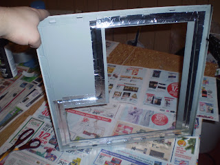
I will start with what I said from last post, about the side panels. All cut up and painted, I just needed to put plexi-glass into those openings. What I use is Picture frame plexi-glass that I find from hardware stores. Home depot sells 18"x24"x1/8" sheets for just under $10.
What some people say to use for cutting is to simply score the sheets with an razor knife, and snap it. This method works when you need rectangular shapes, however one of the shapes as a bit different (the L-shaped windows). So I used my jig-saw with a bi-metal blade to cut the window. This can cause the plexi-glass to melt slightly and make some plastic burning like smells. Nothing terrible, but the results work.
For the L-shaped window
So now to install the window. A lot of people feel the need to bolt or rivet their windows onto their side panels. That's fine, but I absolutely hate looking at fasteners of any kind. My method is duct tape. This may seem very short cut like, or something that should be temporary, but it is not. I have tried many adhesives, but generally find that after moving the case a few times (to LAN parties and back) that the window eventually falls out. Another problem is that adhesive can be messy, while duct tape is easy.
Advantages to duct tape:
- Less drilling
- Cheaper
- No special tools
- A child can do this
- No unsightly fasteners
- No vibration noises
- No potential of cracking said window by over tightening the fasteners
Duct tape to the rescue
Can't even see the plexi-glass
You can only tell that there is plexi-glass in this one from the reflection of the light above
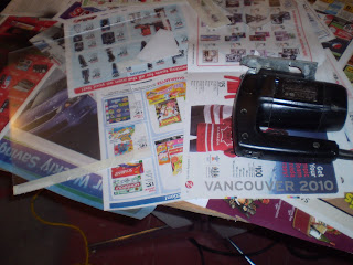
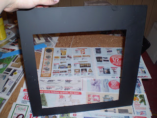
And the front bezel. I do my normal prep work to the bezel by washing with soap and water. Using toothpicks and q-tips to clean grim from the little nooks and crannies. Remove all buttons, LED's, etc...
Prepping the front bezel
And today I am using Dupli-Color's Vinyl and Fabric Dye. This is an automotive product, usually found within the touch up paint sections of you local car store. They make this stuff in multiple colors and finishes. This is flat black, to match the exterior flat black exterior.

Dupli-Color Flat Black Vinyl and Fabric Dye
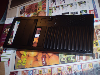
After four coats, it's looking good
With everything installed, here it is!
Done! I have everything installed now, including PSU, mobo, HDD, optical drive, radiator, pump, fill and drain ports, fan controller and fans. Time to leak test!
I would love to make this post all about my over clocking and experience with gaming on this beast, but I figured I should probably post about my story of getting it to this point.
I will start with what I said from last post, about the side panels. All cut up and painted, I just needed to put plexi-glass into those openings. What I use is Picture frame plexi-glass that I find from hardware stores. Home depot sells 18"x24"x1/8" sheets for just under $10.
What some people say to use for cutting is to simply score the sheets with an razor knife, and snap it. This method works when you need rectangular shapes, however one of the shapes as a bit different (the L-shaped windows). So I used my jig-saw with a bi-metal blade to cut the window. This can cause the plexi-glass to melt slightly and make some plastic burning like smells. Nothing terrible, but the results work.
For the L-shaped window
So now to install the window. A lot of people feel the need to bolt or rivet their windows onto their side panels. That's fine, but I absolutely hate looking at fasteners of any kind. My method is duct tape. This may seem very short cut like, or something that should be temporary, but it is not. I have tried many adhesives, but generally find that after moving the case a few times (to LAN parties and back) that the window eventually falls out. Another problem is that adhesive can be messy, while duct tape is easy.
Advantages to duct tape:
- Less drilling
- Cheaper
- No special tools
- A child can do this
- No unsightly fasteners
- No vibration noises
- No potential of cracking said window by over tightening the fasteners
Duct tape to the rescue
Can't even see the plexi-glass
You can only tell that there is plexi-glass in this one from the reflection of the light above
And the front bezel. I do my normal prep work to the bezel by washing with soap and water. Using toothpicks and q-tips to clean grim from the little nooks and crannies. Remove all buttons, LED's, etc...
Prepping the front bezel
And today I am using Dupli-Color's Vinyl and Fabric Dye. This is an automotive product, usually found within the touch up paint sections of you local car store. They make this stuff in multiple colors and finishes. This is flat black, to match the exterior flat black exterior.
Dupli-Color Flat Black Vinyl and Fabric Dye
After four coats, it's looking good
With everything installed, here it is!
Done! I have everything installed now, including PSU, mobo, HDD, optical drive, radiator, pump, fill and drain ports, fan controller and fans. Time to leak test!
I mentioned in the last post that I just made, that the case is complete, and the water cooling loop is read for leak testing. Time to get out of my grubby basement, and into the living room to fill the loop. I have laminate flooring in my living room which requires re finishing so if I spill coolant, or even sulfuric acid on the flooring, I am not damaging anything that I would be upset about.
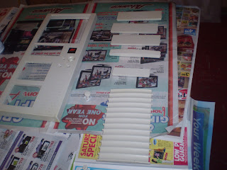
My first task at hand is setting up my test environment. I do not want to be running the system while leak testing (which would negate the leak testing) so I need to "hot wire" an old power supply unit. Just about anyone who hoards old computer parts will have one or two these things. My choice was my "Power Max" 250w power supply. I doubt this thing could handle a 150w load on it, let alone 250w, but that is enough to run my pump.
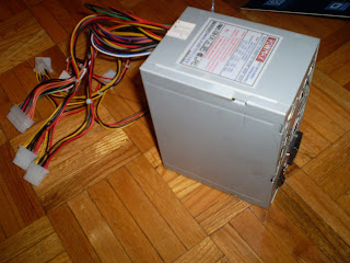
Old power supply unit
Generally you need to jump the green wire (pin 16) to any black ground wire of the main motherboard connector. I use this power supply as a means of testing other things (like fans, case lighting, and now water cooling) so I have actually cut and spliced the green wire to a black wire; I use the main shutoff of the power supply as an on/off switch.
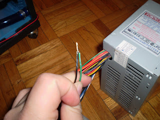
I had to remove the tape to show this. Use electrical tape or heat shrink to cover this
Here I am filling the system through the top fill port
So for some explanation of me filling the loop. as you can see I am using a funnel and turkey baster to put coolant through the fill port. You can order syringe like devices design for PC liquid cooling, but I decided that a trip to the dollar store would suffice. A set of 3 funnels and the turkey baster set me back a whopping two dollars. DO NOT reuse items that come in contact with coolant to handle food.
Now as you can also see, I have one hand filling the system, and another hand on the power switch of the tester PSU. I would hit the switch to turn it on and slowly fill the funnel with fluid until my baster was empty. Normally I would look at the tubing of the fill-port to see where the liquid level is, however the Fesser One UV Blue tubing is way too day to see the liquid.
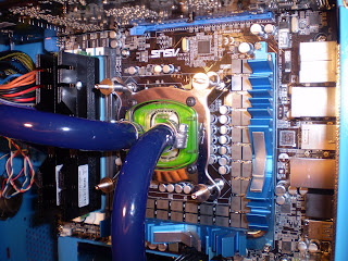
Bubbles in the loop, caught inside the CPU water block
(You may have to visit the blog to see the hi resolution photo [url]http:\\xtremebuild.info[/url])
The only indication of fluid level I can see is through the clear plexi-glass top of the CPU water block. As you can see there are air bubbles in the loop. These can be tricky to remove, usually when first filling a system I will flip the switch for the pump on and off for 10 second periods a few dozen times, adding coolant every handful of power cycles.
I didn't get all the air out of the system, but that is okay. I leak test over usually a 24hour minimum period. I will check on the system every few hours and drop coolant into the fill port while the system is on. Even after I am using the system, I will hear for the pump catching air bubble when I initially turn on a system to know when to top the loop off with coolant.
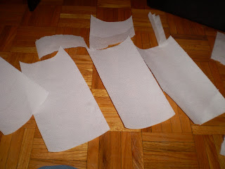
For the leak test I like to use white paper towel. I lay paper towel all over the bottom over the case, making sure to keep under where ever there is a tubing connection, including T or Y adapters.
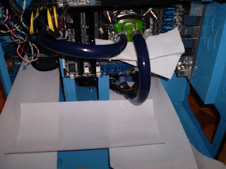
Laying down the paper towel
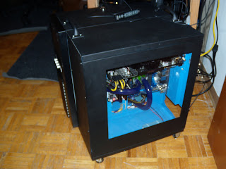
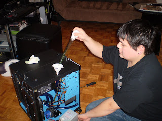
Now to put the computer into a safe place, and leave it for 24hours. For some added bling, I played around with the uv cathodes I had for the case. My girlfriend got a shot of me waving them around like light sabers.

Special needs Jedi
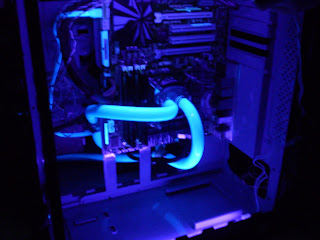
Preview of how the UV setup will look
Checking for green stains
After 24 hours. I do a paper towel inspection. Since I used green coolant, I am looking for any hints of green liquid stains. I also do a quick look checking near all the tubing connections, to make sure they are dry, and not wet. Since bubbles are still being worked through the system, it is impossible to tell if there is a leak if the coolant level seemed to drop.
I had no indication of fluid leaks, which is good! Some people like to leak test systems over a few days, however if it didn't within 24 hours, I doubt it will ever leak.
As an added bonus of playing around with UV light sources. A cool item to try is Tonic Water, which is different than Club Soda and Soda Water. It seems to glow a super light blue.
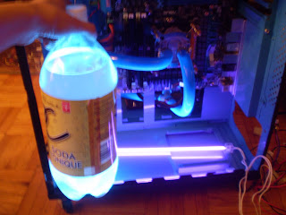
Tonic Water + UV light = Saturday night entertainment
My first task at hand is setting up my test environment. I do not want to be running the system while leak testing (which would negate the leak testing) so I need to "hot wire" an old power supply unit. Just about anyone who hoards old computer parts will have one or two these things. My choice was my "Power Max" 250w power supply. I doubt this thing could handle a 150w load on it, let alone 250w, but that is enough to run my pump.
Old power supply unit
Generally you need to jump the green wire (pin 16) to any black ground wire of the main motherboard connector. I use this power supply as a means of testing other things (like fans, case lighting, and now water cooling) so I have actually cut and spliced the green wire to a black wire; I use the main shutoff of the power supply as an on/off switch.
I had to remove the tape to show this. Use electrical tape or heat shrink to cover this
Here I am filling the system through the top fill port
So for some explanation of me filling the loop. as you can see I am using a funnel and turkey baster to put coolant through the fill port. You can order syringe like devices design for PC liquid cooling, but I decided that a trip to the dollar store would suffice. A set of 3 funnels and the turkey baster set me back a whopping two dollars. DO NOT reuse items that come in contact with coolant to handle food.
Now as you can also see, I have one hand filling the system, and another hand on the power switch of the tester PSU. I would hit the switch to turn it on and slowly fill the funnel with fluid until my baster was empty. Normally I would look at the tubing of the fill-port to see where the liquid level is, however the Fesser One UV Blue tubing is way too day to see the liquid.
Bubbles in the loop, caught inside the CPU water block
(You may have to visit the blog to see the hi resolution photo [url]http:\\xtremebuild.info[/url])
The only indication of fluid level I can see is through the clear plexi-glass top of the CPU water block. As you can see there are air bubbles in the loop. These can be tricky to remove, usually when first filling a system I will flip the switch for the pump on and off for 10 second periods a few dozen times, adding coolant every handful of power cycles.
I didn't get all the air out of the system, but that is okay. I leak test over usually a 24hour minimum period. I will check on the system every few hours and drop coolant into the fill port while the system is on. Even after I am using the system, I will hear for the pump catching air bubble when I initially turn on a system to know when to top the loop off with coolant.
For the leak test I like to use white paper towel. I lay paper towel all over the bottom over the case, making sure to keep under where ever there is a tubing connection, including T or Y adapters.
Laying down the paper towel
Now to put the computer into a safe place, and leave it for 24hours. For some added bling, I played around with the uv cathodes I had for the case. My girlfriend got a shot of me waving them around like light sabers.
Special needs Jedi
Preview of how the UV setup will look
Checking for green stains
After 24 hours. I do a paper towel inspection. Since I used green coolant, I am looking for any hints of green liquid stains. I also do a quick look checking near all the tubing connections, to make sure they are dry, and not wet. Since bubbles are still being worked through the system, it is impossible to tell if there is a leak if the coolant level seemed to drop.
I had no indication of fluid leaks, which is good! Some people like to leak test systems over a few days, however if it didn't within 24 hours, I doubt it will ever leak.
As an added bonus of playing around with UV light sources. A cool item to try is Tonic Water, which is different than Club Soda and Soda Water. It seems to glow a super light blue.
Tonic Water + UV light = Saturday night entertainment
So, for the fun part. For the last few days I have been having fun playing with all the ASUS tools for overclocking, as,well as reading other people's experience with LGA1156 CPU's.
First I decided to let the Turbo Evo's Auto Tune feature work some magic and see what an automatic tuning program would do. After leaving it for an hour, it came back with a stable overclock between 3.6ghz and 3.7ghz. Not too shabby in my opinion. But what I have read is people pushing their processors to 3.9ghz and even 4.0ghz using stock cooling with this CPU. I know not all CPU's are created equal, but using water cooling means I should be able to do better than stock air cooling, right?
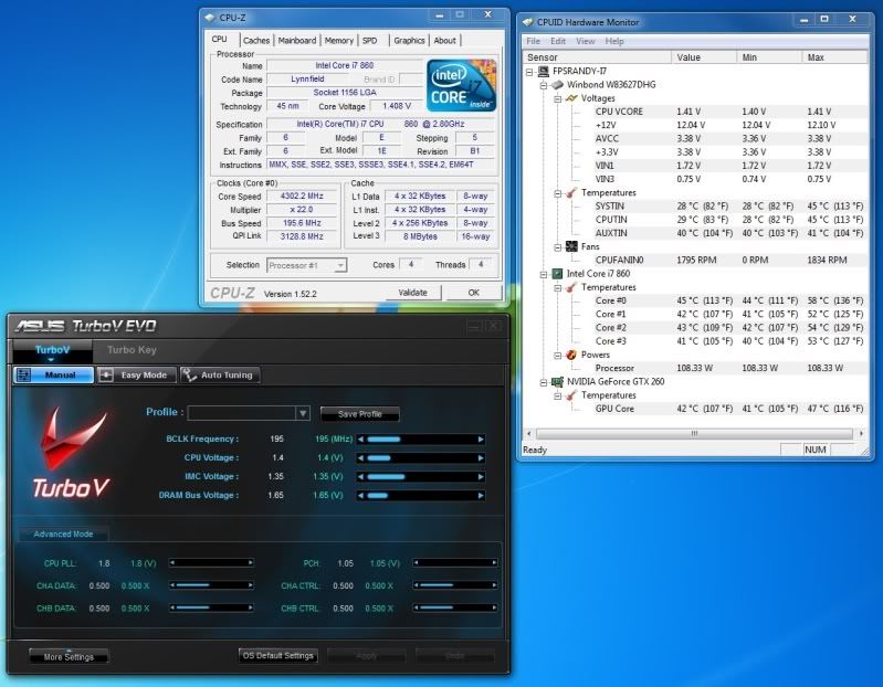
4.4ghz on four cores!
After tinkering for about 30 minutes I got this. 200mhz bclk (base clock), 22x multiplier, and just under 1.4v to the vcore. This was pretty stable, I managed a who slew of benchmarks without fail.
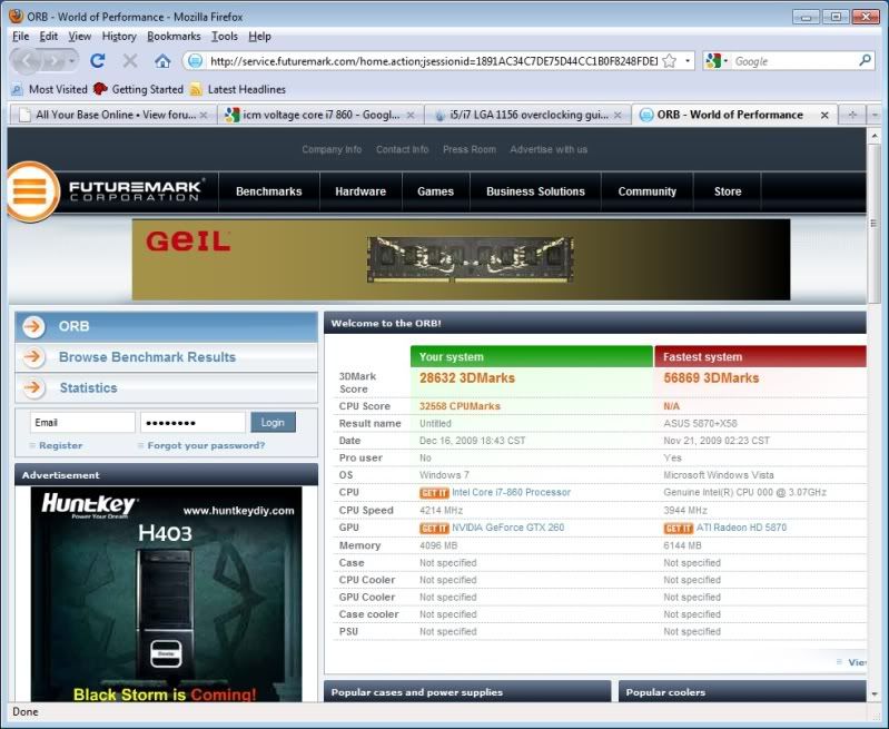
3DMark05: 28,632
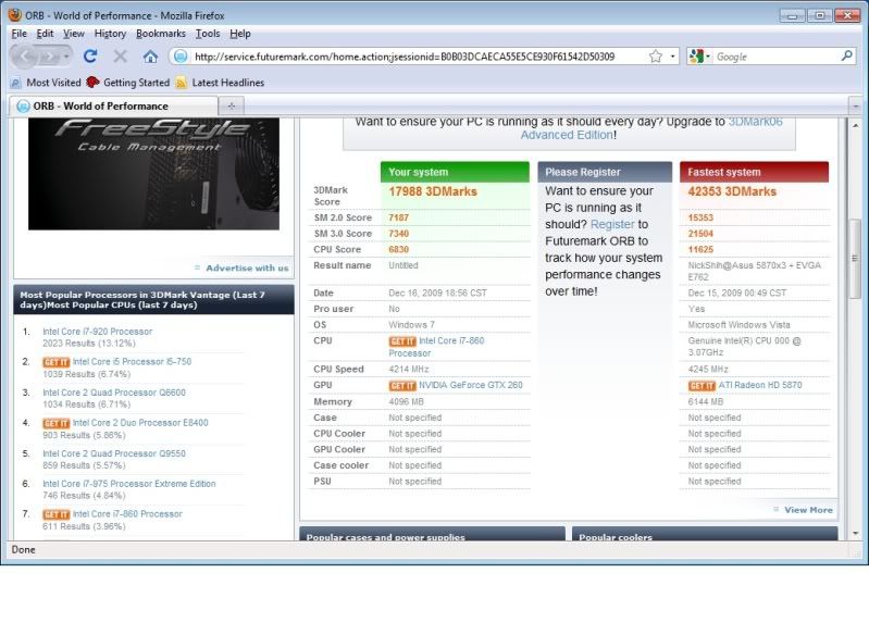
3DMark06: 17988
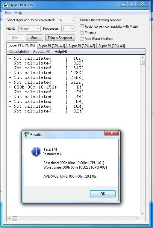
HyperPi 1M: AVG. 10.148s
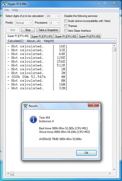
HyperPi 4M: AVG. 53.094 Seconds
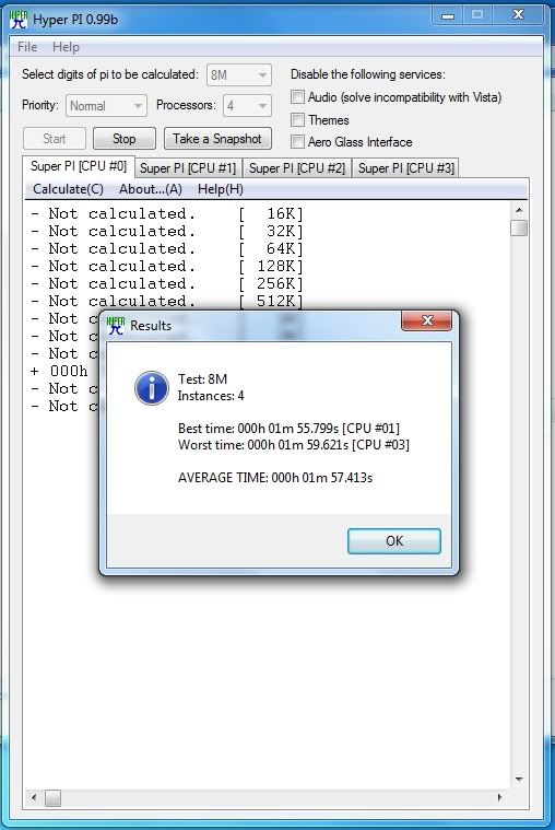
HyperPi 8M: AVG. 1 Minute, 57.413 Seconds
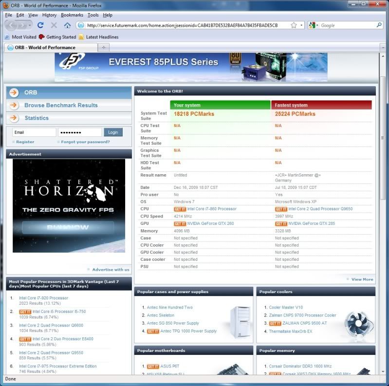
PCMark06: 18,218
Wow, blows my old computer right out of the water. Nearly 3 times the score on Futuremark tests, and half the time for my Dual core to run HyperPi tests.
But is it stable? This is a funny topic of discussion, because people will describe it differently. If you machine does not blue screen or lock up while idling or under normal load, and the computer will not blue screen or lockup during benchmark tests, are both acceptable to some people for determining a "stable" system.
A third way to test for stability is Prime95. Prime 95 gets your systems to crunch number as fast as it can while being pushed down its knees in calculations. It compares to calculations to known correct answers to check if a system is stable.
Unfortuantely my current 4.4ghz clock rate was not stable after 2 hours of torture tests from Prime 95, I was seeing calculation errors
Now, most would say to add more to the vcore of your chip. For me, I was at the upper limits of what I was comfortable with for a vcore. I know many would push their voltage further, and I have seen higher clocks achieved by doing so. For me, I want to find the overclock that will stay stable as I run it for day to day use.
See this article: http://www.anandtech.com/mb/showdoc.aspx?i=3661
After reading that article and some forums posts online, I got scared to run past Intel's recommended voltages for the cpu (See: http://processorfinder.intel.com/detail ... Spec=SLBJJ and the VID Voltage range). The ASUS P7P55D Premium seems to unfortunately have a Foxconn CPU socket. Not cool...
I ended up lower the blck speed to something a bit more stable (195mhz) with 1.4V on the Vcore.
4.3Ghz on four cores!
Now, I have hyper-threading, turbo boost and speed step turned off. Speed step and Turbo Boost are two features that I felt that overclocks would not need or care about at all. What I was torn on, was Hyper threading.
Since I would primarily be gaming, and most software and games currently available do not work with multiple cores very well as it is, I decided ultimately I would disable hyper threading to squeeze a few more mhz on the blck, while keeping under 1.4V on the vcore.
I decided 1.4V was my absolute maximum voltage of my overclock with this motherboard. Notice I said mother board, and not chip... All because of the Foxconn socket issues. If I were to fry the CPU would be one thing, melting the cpu socket and burning the CPU is two things.
I am not sure if ASUS would warranty a board if anyone were to melt the cpu socket from overclocking. They seem like a great company, but I would not feel ethically right to RMA a board for so, and I do not posses the funds for a new board and CPU if I did do so.
On the other hand, the ASUS TurboV Easy Mode tool, seems to set the vcore at 4.5 mhz. This may or may not be an oversight on ASUS' part, but I still do not feel comfortable being above 1.4V, or at least having it over 1.4V for an extended period of time.
Now, for benchmarks for the 4.3ghz you ask? why? the score will be lower, and really, 100mhz less speed is less than 2.5% decrease on the CPU's performance. I'm really not a bench marker for comparing my system to others. I'm a tinkerer and video game player; it was fun to play with the over clocking settings, but If I over clocked and screen shotted every overclock I performed, I would a few weeks to myself, and most likely would go insane.
As more information comes in about overclocking the Core i7 860 CPU, I will look into ways of increasing the clock speeds. For now I am going to go kill zombies in Left 4 Dead 2, and shoot some Nazi Zombies in World at War.
First I decided to let the Turbo Evo's Auto Tune feature work some magic and see what an automatic tuning program would do. After leaving it for an hour, it came back with a stable overclock between 3.6ghz and 3.7ghz. Not too shabby in my opinion. But what I have read is people pushing their processors to 3.9ghz and even 4.0ghz using stock cooling with this CPU. I know not all CPU's are created equal, but using water cooling means I should be able to do better than stock air cooling, right?
4.4ghz on four cores!
After tinkering for about 30 minutes I got this. 200mhz bclk (base clock), 22x multiplier, and just under 1.4v to the vcore. This was pretty stable, I managed a who slew of benchmarks without fail.
3DMark05: 28,632
3DMark06: 17988
HyperPi 1M: AVG. 10.148s
HyperPi 4M: AVG. 53.094 Seconds
HyperPi 8M: AVG. 1 Minute, 57.413 Seconds
PCMark06: 18,218
Wow, blows my old computer right out of the water. Nearly 3 times the score on Futuremark tests, and half the time for my Dual core to run HyperPi tests.
But is it stable? This is a funny topic of discussion, because people will describe it differently. If you machine does not blue screen or lock up while idling or under normal load, and the computer will not blue screen or lockup during benchmark tests, are both acceptable to some people for determining a "stable" system.
A third way to test for stability is Prime95. Prime 95 gets your systems to crunch number as fast as it can while being pushed down its knees in calculations. It compares to calculations to known correct answers to check if a system is stable.
Unfortuantely my current 4.4ghz clock rate was not stable after 2 hours of torture tests from Prime 95, I was seeing calculation errors
Now, most would say to add more to the vcore of your chip. For me, I was at the upper limits of what I was comfortable with for a vcore. I know many would push their voltage further, and I have seen higher clocks achieved by doing so. For me, I want to find the overclock that will stay stable as I run it for day to day use.
See this article: http://www.anandtech.com/mb/showdoc.aspx?i=3661
After reading that article and some forums posts online, I got scared to run past Intel's recommended voltages for the cpu (See: http://processorfinder.intel.com/detail ... Spec=SLBJJ and the VID Voltage range). The ASUS P7P55D Premium seems to unfortunately have a Foxconn CPU socket. Not cool...
I ended up lower the blck speed to something a bit more stable (195mhz) with 1.4V on the Vcore.
4.3Ghz on four cores!
Now, I have hyper-threading, turbo boost and speed step turned off. Speed step and Turbo Boost are two features that I felt that overclocks would not need or care about at all. What I was torn on, was Hyper threading.
Since I would primarily be gaming, and most software and games currently available do not work with multiple cores very well as it is, I decided ultimately I would disable hyper threading to squeeze a few more mhz on the blck, while keeping under 1.4V on the vcore.
I decided 1.4V was my absolute maximum voltage of my overclock with this motherboard. Notice I said mother board, and not chip... All because of the Foxconn socket issues. If I were to fry the CPU would be one thing, melting the cpu socket and burning the CPU is two things.
I am not sure if ASUS would warranty a board if anyone were to melt the cpu socket from overclocking. They seem like a great company, but I would not feel ethically right to RMA a board for so, and I do not posses the funds for a new board and CPU if I did do so.
On the other hand, the ASUS TurboV Easy Mode tool, seems to set the vcore at 4.5 mhz. This may or may not be an oversight on ASUS' part, but I still do not feel comfortable being above 1.4V, or at least having it over 1.4V for an extended period of time.
Now, for benchmarks for the 4.3ghz you ask? why? the score will be lower, and really, 100mhz less speed is less than 2.5% decrease on the CPU's performance. I'm really not a bench marker for comparing my system to others. I'm a tinkerer and video game player; it was fun to play with the over clocking settings, but If I over clocked and screen shotted every overclock I performed, I would a few weeks to myself, and most likely would go insane.
As more information comes in about overclocking the Core i7 860 CPU, I will look into ways of increasing the clock speeds. For now I am going to go kill zombies in Left 4 Dead 2, and shoot some Nazi Zombies in World at War.
First of all, I would like to thank all the Sponsors for donating prizes for this contest. ASUS gets a huge shout out for organizing the contest. The sponsors Would include: Antec, ASUS, Intel, G.Skills, Nvidia, Razer, and Samsung. I have used all your products in the past, and am still impressed with the quality and performance of them.
So, after having and using the completed build for the last few days, I have finally settled on a final overclock. 4.3Ghz seems to be acceptable for stability and temperatures. I would use the system at 4.4 or 4.5ghz, but the stability worries me for having using it over a long period of time.
My biggest regret for the project is not checking into the water block for the gpu. Air cooling is so yesterday in my books for a system described as "Xtreme". As a result I have not overclocked the gpu at all. However there really does not seem to be a huge need to, every video game I have played I have been able to crank the video settings as high as it can go with out once having huge frame rate drops, or running below 60 fps.
Now the motherboard I believe made a huge impact for the ability to overclock this system. The 48 phase power design seems to do what it is advertised to do. Keep stable power to ensure stable overclocks. The T. Probe feature seems like a god send. There is a T. Probe utility for windows which allows you to see the temperature for the 32 VRM's for the processor and watch how the heat fluctuates as the power changes on each VRM.
Some other great noteworthy features of the motherboard were the Power and Reset buttons that are on the board. These are not something one would use on a daily bases, but when you are beginning your build and testing some things, it is definitely handy to have those two buttons around. Another cool button was the A-OK button which would try to find stable timings for your ram if you became overzealous playing with ram timings.
I have mixed feelings for the Turbo V Evo. It was awesome to be able to overclock your processor real time while in windows. The Auto Tuning feature I can see as being a great tool for people who are new to overclocking and do not want to spend time reading and testing. For more advance users who have some overclocking experience (intermediate and up) this was not a very useful feature, as it is possible to add a lot more base-clock than what the utility would do. The windows utility also seemed to be missing a lot of options that affect your overclock that you could only reach in the bios (this was probably why the auto tuning feature was not as good as manually overclocking).
Which brings me to talking about the Turbo V Remote. I see what the Turbo V Remote is suppose to do, but I was not able to use the remote for what I wanted to do. I wanted to have 3 over clocking profiles. A profile to use when I am surfing the net and not utilizing the entire cpu. Second profile would be my 4.3ghz Stable over clock. The last setting would be the 4.5ghz "questionably stable" profile which would be used for when I really need a few extra clock cycles (stock cpu speeds for example). The problem I had with the remote was that the difference between the first low power setting and the second 4.3ghz setting was such a change, that my system would immediately lock up. The handiest button was then the power button located on the remote that you could hold down and have your system shut down. The bus speed buttons worked as they seem they would (they adjusted the base clock speeds, and nothing else) but again large clock speed changes caused the system to lock up again.
The last feature of the board that I do not have much to say about is the EPU feature. This is a power saving feature. In my opinion it seemed kinda odd to have bundled with a motherboard that advertises as a board to overclock with. Generally I am not concerned with the amount of the power that my system uses if I am overclocking, because I already know it will be higher than most similar PC's. I also can not comment on how much it actually drops power usage of the system, as I did not have any tools that would measure how much the power supply was drawing. I really need to get something like: http://www.thinkgeek.com/gadgets/travelpower/7657/
Since we are talking about power, lets talk about Antec's 850w Quattro PSU. This was a modular PSU, which allowed for removing clutter from the inside of your system. One of the things I though Antec could have improved on with the modular connectors was to make it so you could chose if you needed the 4pin or 8pin CPU power connector. I have also seen other manufactures split the connector so you could use it as either, much like 6pin and 8pin pci-e power connectors. Other than that, the fan inside the unit seems to be quiet as advertised, and according to hardware monitor the power seems to coming in within tolerances and they do not significantly change when I begin to work the system harder.
Other notable components in the system would be the ram from G.Skills. The ram is absolutely amazing. It has one of the highest speed ratings of 2133mhz. At one point I was over clocking and was able to run it near 2300mhz (changing base clock and memory dividers, changes the speed at which the ram will run). This allowed for a great deal of versatility when overclocking while keeping a high level of memory performance.
Next is Razer's contribution; The Lycosa keyboard and Death Adder mouse. I am a huge fan of Razer products. I was actually using the Lachesis mouse of theirs, and recently purchased the Carcharias headset as well as their Mantis Control mouse pad. The mouse is nice feeling in the hand like all their mice have been in the past.
This is however my first Razer keyboard. The first thing that sticks out is the backlit keys, the backlight can be turned on and off as desired on the key board. The WASD keys can lit on their own for gaming. The next thing is the USB and audio ports. These are for pluging your mouse and headset into. However I ended up plugging my mouse directly to the back of my computer. I liked having the usb port open for using other devices with(such as a usb memory stick, digital camera, ipod, etc...).
Now that I am done talking about the Sponsored prizes, some pictures of the final build.
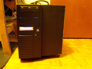
Front

Right Side
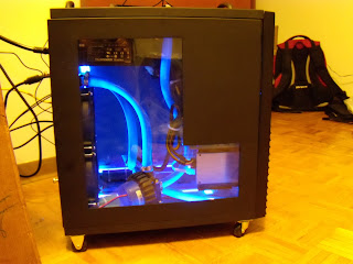
Left Side
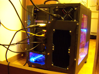
Back
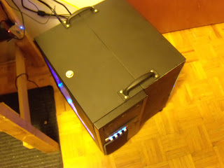
Top
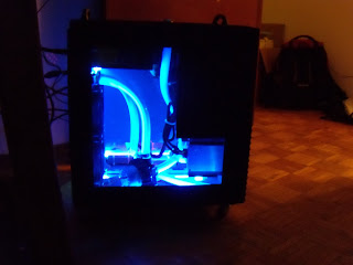
Lights Off, Left Side
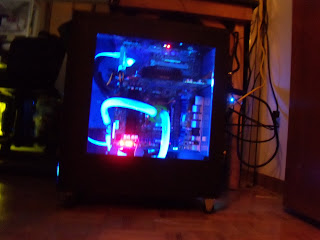
Lights Off, Right Side
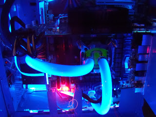
Interior Close Up
Thank you again to all the sponsors! I could not have done it without you!
http://xtremebuild.info
So, after having and using the completed build for the last few days, I have finally settled on a final overclock. 4.3Ghz seems to be acceptable for stability and temperatures. I would use the system at 4.4 or 4.5ghz, but the stability worries me for having using it over a long period of time.
My biggest regret for the project is not checking into the water block for the gpu. Air cooling is so yesterday in my books for a system described as "Xtreme". As a result I have not overclocked the gpu at all. However there really does not seem to be a huge need to, every video game I have played I have been able to crank the video settings as high as it can go with out once having huge frame rate drops, or running below 60 fps.
Now the motherboard I believe made a huge impact for the ability to overclock this system. The 48 phase power design seems to do what it is advertised to do. Keep stable power to ensure stable overclocks. The T. Probe feature seems like a god send. There is a T. Probe utility for windows which allows you to see the temperature for the 32 VRM's for the processor and watch how the heat fluctuates as the power changes on each VRM.
Some other great noteworthy features of the motherboard were the Power and Reset buttons that are on the board. These are not something one would use on a daily bases, but when you are beginning your build and testing some things, it is definitely handy to have those two buttons around. Another cool button was the A-OK button which would try to find stable timings for your ram if you became overzealous playing with ram timings.
I have mixed feelings for the Turbo V Evo. It was awesome to be able to overclock your processor real time while in windows. The Auto Tuning feature I can see as being a great tool for people who are new to overclocking and do not want to spend time reading and testing. For more advance users who have some overclocking experience (intermediate and up) this was not a very useful feature, as it is possible to add a lot more base-clock than what the utility would do. The windows utility also seemed to be missing a lot of options that affect your overclock that you could only reach in the bios (this was probably why the auto tuning feature was not as good as manually overclocking).
Which brings me to talking about the Turbo V Remote. I see what the Turbo V Remote is suppose to do, but I was not able to use the remote for what I wanted to do. I wanted to have 3 over clocking profiles. A profile to use when I am surfing the net and not utilizing the entire cpu. Second profile would be my 4.3ghz Stable over clock. The last setting would be the 4.5ghz "questionably stable" profile which would be used for when I really need a few extra clock cycles (stock cpu speeds for example). The problem I had with the remote was that the difference between the first low power setting and the second 4.3ghz setting was such a change, that my system would immediately lock up. The handiest button was then the power button located on the remote that you could hold down and have your system shut down. The bus speed buttons worked as they seem they would (they adjusted the base clock speeds, and nothing else) but again large clock speed changes caused the system to lock up again.
The last feature of the board that I do not have much to say about is the EPU feature. This is a power saving feature. In my opinion it seemed kinda odd to have bundled with a motherboard that advertises as a board to overclock with. Generally I am not concerned with the amount of the power that my system uses if I am overclocking, because I already know it will be higher than most similar PC's. I also can not comment on how much it actually drops power usage of the system, as I did not have any tools that would measure how much the power supply was drawing. I really need to get something like: http://www.thinkgeek.com/gadgets/travelpower/7657/
Since we are talking about power, lets talk about Antec's 850w Quattro PSU. This was a modular PSU, which allowed for removing clutter from the inside of your system. One of the things I though Antec could have improved on with the modular connectors was to make it so you could chose if you needed the 4pin or 8pin CPU power connector. I have also seen other manufactures split the connector so you could use it as either, much like 6pin and 8pin pci-e power connectors. Other than that, the fan inside the unit seems to be quiet as advertised, and according to hardware monitor the power seems to coming in within tolerances and they do not significantly change when I begin to work the system harder.
Other notable components in the system would be the ram from G.Skills. The ram is absolutely amazing. It has one of the highest speed ratings of 2133mhz. At one point I was over clocking and was able to run it near 2300mhz (changing base clock and memory dividers, changes the speed at which the ram will run). This allowed for a great deal of versatility when overclocking while keeping a high level of memory performance.
Next is Razer's contribution; The Lycosa keyboard and Death Adder mouse. I am a huge fan of Razer products. I was actually using the Lachesis mouse of theirs, and recently purchased the Carcharias headset as well as their Mantis Control mouse pad. The mouse is nice feeling in the hand like all their mice have been in the past.
This is however my first Razer keyboard. The first thing that sticks out is the backlit keys, the backlight can be turned on and off as desired on the key board. The WASD keys can lit on their own for gaming. The next thing is the USB and audio ports. These are for pluging your mouse and headset into. However I ended up plugging my mouse directly to the back of my computer. I liked having the usb port open for using other devices with(such as a usb memory stick, digital camera, ipod, etc...).
Now that I am done talking about the Sponsored prizes, some pictures of the final build.
Front
Right Side
Left Side
Back
Top
Lights Off, Left Side
Lights Off, Right Side
Interior Close Up
Thank you again to all the sponsors! I could not have done it without you!
http://xtremebuild.info