Sigma One--pretty much dead silent for WWW, E-mail and Music

Show off your quiet rig.

Moderators: NeilBlanchard, Ralf Hutter, sthayashi, Lawrence Lee

Edward Ng
SPCR Reviewer
Posts: 2696
Joined: Thu Dec 11, 2003 9:53 pm
Location: Scarsdale, NY
Contact:

Post by Edward Ng » Tue Mar 09, 2004 12:57 pm

This post is not entirely new stuff; I'm just bringing over content from this thread.

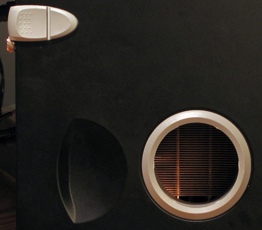
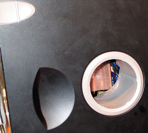
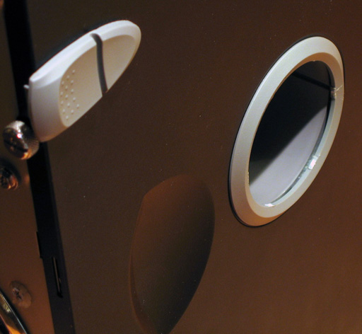
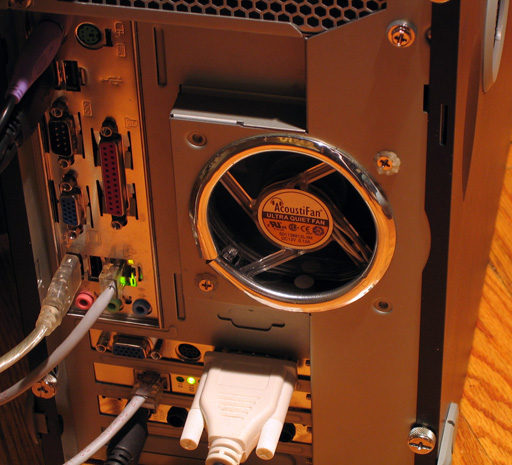
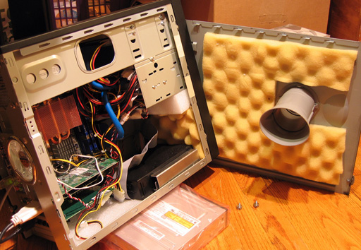
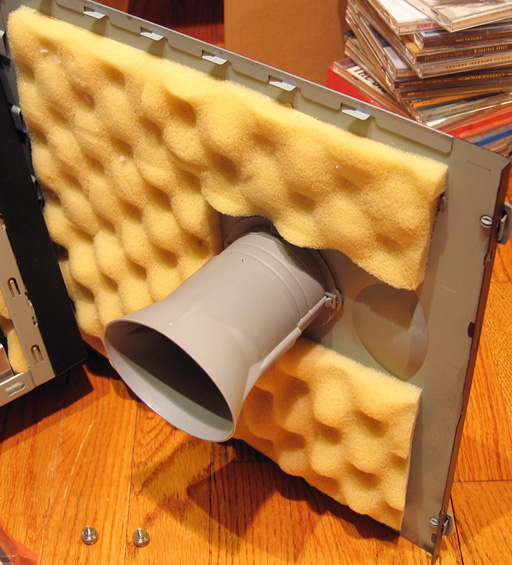
The side duct on Sigma One consists of a circular perforated section on the side panel, with a plastic, "garnish," ring outside and the extendable duct on the inside. The exhaust of the case had your typical punched grill. I decided to buy a set of Wiss tin snips and cut those grills out, to improve air flow. Being that the very, very quiet fan spins at such low speed, I figured that cutting the grills would probably help some, so I completely cut out the exhaust grill, and then I completely cut out the perforated sheet blocking the intake duct and completely removed the center portion of the intake shield so it's wide open.

Boy, I sure underestimated how important killing grills is.

These were my before temps:
Image
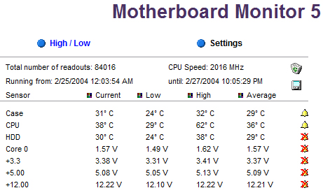
62C peak temp after a couple hours of Prime95 High Heat Test. That is actually decent, considering I don't have a fan mounted on the CPU HS.

And these were my after temps:
Image
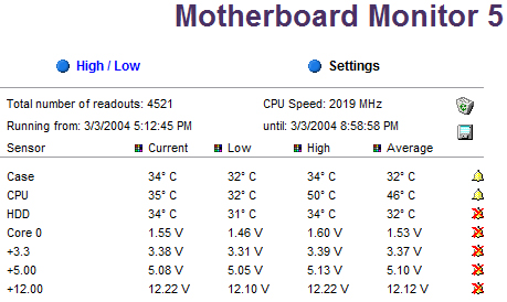
The peak temp, after a few hours of Prime95 High Heat Test, is now only 50C.

Ladies and gentlemen, that's a 12C drop in peak temp, just buy cutting out some grills; talk about kick-ass!

I must admit, again, I never expected such incredible results. I knew the intake duct was restricted, but I never expected such a dramatic improvement; maybe 5C at best. My only explaination is that the duct is the only intake in the system, it all blows right onto the HS of the CPU, and then gets the hot stuff sucked straight out the back. I actually feel much more air coming out the back with my hand now.

All in all, a worthy bit of effort. :D

-Ed

EDIT: Typos, as usual.

More EDIT: Formatting and grammar.

Edward Ng
SPCR Reviewer
Posts: 2696
Joined: Thu Dec 11, 2003 9:53 pm
Location: Scarsdale, NY
Contact:

Post by Edward Ng » Thu Mar 11, 2004 10:35 pm

Finally, the pictures of the air flow improvement mods done in my last update to this thread...

Here's how the side intake duct looks after the mod; see earlier shots in this thread for a before shot.
Image
That's how it looks from the same exact angle now. Completely clear; the heatsink is clearly visible now, no longer obscured by two layers of blockage.

Image
Another shot, from a slight angle, with the flash enabled to really clarify what's going on.

Image
Finally, this sharp angle shot shows you the gap left between the interior duct part and the outside ring part that remains where the perforated portion of the side panel used to gap through. Also noticeable is the portion of remaining ring that the center plastic grill used to attach (it was a single piece, the ring and the grill; I cut the grill off with the tin snips and then cleaned it up with a tiny pair of wire cutters).


That's the side duct, and here's how the rear exhaust looks after modding; again, see earlier in the thread for the before shot:
Image
I'm not too great yet at closing the seam where the two ends of the molding meet up, so it's not nearly as nice as Seal's work on his rig, but I like the chrome effect!


And now, for some more gratuitous shots I took along with the above ones:
Image
A shot with the side panel next to the system interior; you can see the, "egg crate," foam that I lined the case panels with, as well as the SilentDrive enclosure that has the Fujitsu MHT2080AT inside. The whole thing, as you can see, sits on a double-thick layer of the foam I used to use to enclose my Samsung SP1614N with the Zalman ZM-2HC1 into when I had them locked into the lower half-height bay. Also visible is the duct extension that leads into the system; you can see how it's adjustable in length.

Image
This is a closer look at the duct and the egg crate foam liner.

Image
A closer shot of the SilentDrive, the egg crate foam lining the front of the case and also the block of packing foam that I used to have the Samsung SP1614N sitting on after I moved it out of that half-height bay. Now I use it just to fill up the gap between the underside of the 3.5" drive bay and the top of the egg crate foam lining the front.

Image
Last but not least, an overall shot of the system.


I hope these images shed a little light on my work; until Antec releases their Phantom to the market and I read a few reviews, I think this ends my modding for the meantime.

-Ed

PS If you want closer/larger versions of the shots above, all you have to do is look at the URL for all the shots above. They all end in SPCR before the .jpg extension; if you try the same URL but cut out the SPCR letters before .jpg, your browser will load the larger version of the images. When I get around to it, I'll be posting both versions of these pictures at my web site, but I'm a little too tired to do all that work tonight.

Xspringe
Posts: 50
Joined: Mon Feb 16, 2004 11:22 am

Post by Xspringe » Fri Mar 12, 2004 4:44 am

Amazing work, that is exactly what I'd like my studio computer to be like, save for the HD suspension mechanism.

What is the width of the case? I need to know because my studio computer will be placed inside the wall with limited space available.

I wish there was a Dutch store that sold the components I need to recreate your case....

Edward Ng
SPCR Reviewer
Posts: 2696
Joined: Thu Dec 11, 2003 9:53 pm
Location: Scarsdale, NY
Contact:

Post by Edward Ng » Fri Mar 12, 2004 8:40 pm

The case is precisely 7" wide, but the duct protrudes an additional 0.25". I'd recommend leaving it plenty of breathing room on its right side (your left when facing the case directly) anyway, so that the duct can do its work unhindered.

-Ed

BTW the case is 14" tall and 16" deep.

EDIT: I think I should probably outline what the specifications are now, since the specs at the beginning of this thread are now massively defunct:

Here are the system specifications:

InWin IW-523G black steel microATX minitower enclosure, lined with, "egg crate," foam, with the stock exhaust fan replaced using an AcoustiFan AF80CT,

Fortron FSP300-60PN PSU, with stock fan replaced using an undervolted AF120CT,

ASUStek P4B533-VM microATX i845G-based socket-478 mainboard,

Intel Pentium 4 2.0A, passively cooled using a ducted Thermalright SP-94,

Visiontek Xtasy Radeon 9600 adapter, passively cooled,

Fujitsu MHT2080AT, mounted inside a SilentDrive enclosure, resting on foam at the case floor

and two 512MB pieces of Kingston HyperX PC4000 DDR SDRAM.

Xspringe
Posts: 50
Joined: Mon Feb 16, 2004 11:22 am

Post by Xspringe » Mon Mar 29, 2004 1:17 pm

Doesn't it get very dusty inside due to the lack of filters?

I'd say a nice mod would be to bring up the cpu-duct intake up 120mm and adding some sort of filter. The end of the duct (cpu side) should remain the same diameter though. I expect that this would result in approximately the same cooling performance (because the duct will have similar effective throughput) but without the dust buildup inside.

Edward Ng
SPCR Reviewer
Posts: 2696
Joined: Thu Dec 11, 2003 9:53 pm
Location: Scarsdale, NY
Contact:

Post by Edward Ng » Mon Mar 29, 2004 1:29 pm

As a matter of fact, my machines collect virtually zero dust due to the nature of the environment; we have no carpeting in our apartment, and only minimal rugs, just to pass the required minimum for our co-op. The low intake flow of the system, combined with the raised position of the duct at the side combine to reduce dust intake as well...

I've worked on many hundreds of computers in my time, and it's the owners of computers who have carpeted homes, and place their computers right on the floor, that develop the most dust; particularly, tons of dust collect in the lower front intakes, and all the dust that manages to pass through then collects in every possible (and seemingly impossible) corner of the interior, and then onto the exhaust grill.

I'm lucky enough to live in a very low-dust environment.

-Ed

retrofitter
Posts: 6
Joined: Tue May 31, 2005 10:26 pm
Location: Sydney AU
Contact:

Post by retrofitter » Sat Jun 04, 2005 2:49 am

Your wiring in those those shots are unsafe. The pvc insulation of the thermistor wire is only rated to 60deg C, and during operation the heatsink you have attached it to can get hotter than that (up to 100deg) , or if the fan fails, or you introduce a new load etc. The heatsink is also often live on on most power supplies, potentially connecting AC mains up to your 12v rail. This is isn't a risk for you however, just the components inside your PC.
The solution is to use some rtv sealant (white goop), thats often rated to 200c, to glue the sensor to the heatsink. This provides sufficient thermal contact. Good power supplies also use a piece of acetate sheeting (over head projector stuff) where wires and chokes come in close proximity to heatsink.

Also I noticed the wiring for the fan was touching the switch terminals of the PSU. Although the insulation might withstand the 115vac, it blows the common mode 3KV isolation between AC input and output out of the water. The consequences of this are that common mode power surges can fuck your PC more easily. Also mechanical vibration will eventually work away at the insulation causing a fault. It was a common fault of the golden orb cooler to have the wires short out on the fins of the heatsink and blow the fan header because of this.

Edward Ng
SPCR Reviewer
Posts: 2696
Joined: Thu Dec 11, 2003 9:53 pm
Location: Scarsdale, NY
Contact:

Post by Edward Ng » Sat Jun 04, 2005 4:35 am

I no longer use this PSU in my silent rig, and I no longer do PSU fan swaps with thermistored fans.

-Ed

Post Reply