
Is the only manufactured power adapter you can use for the picoPSU-120 the one you buy with it on mini-box? They are out of the larger wattage ones so I was wondering if anyone had any success buying alternate bricks?
Does anyone know the size of the part the brick plugs into on the picoPSU-120?
Thanks!
Brick for picoPSU-120
Moderators: NeilBlanchard, Ralf Hutter, sthayashi, Lawrence Lee, Devonavar
I'm using a Dell DA-2 200W brick that I picked up on ebay for about £20. I'm not actually using the Pico-120 as it turned out to be inadequate for my system, so I got an EF-28 200w board instead but the DA-2 worked fine with the Pico-120 when I tested it and that combo has worked fine for others here.
I think the Pico-120's power input is a 5mm/2.5mm barrel socket but you can easily snip that off and splice in a different connector to fit whatever brick you get. The DA-2's 6-pin connector fits into part of a female ATX connector, so I just bought a ATX extension/conversion cable and cut one end off.
I think the Pico-120's power input is a 5mm/2.5mm barrel socket but you can easily snip that off and splice in a different connector to fit whatever brick you get. The DA-2's 6-pin connector fits into part of a female ATX connector, so I just bought a ATX extension/conversion cable and cut one end off.
Thanks for the tip.doveman wrote:I'm using a Dell DA-2 200W brick that I picked up on ebay for about £20. I'm not actually using the Pico-120 as it turned out to be inadequate for my system, so I got an EF-28 200w board instead but the DA-2 worked fine with the Pico-120 when I tested it and that combo has worked fine for others here.
I think the Pico-120's power input is a 5mm/2.5mm barrel socket but you can easily snip that off and splice in a different connector to fit whatever brick you get. The DA-2's 6-pin connector fits into part of a female ATX connector, so I just bought a ATX extension/conversion cable and cut one end off.
I would not be able to make one of these adapters without explicit step by step instructions with pictures of where all the wires go.
If I were to buy one of these http://www.svc.com/cbl-extend-8p.html to fit the DA-2
and one of these http://www.svc.com/cbl-extend-12v.html to fit the 4pin on the PicoPSU
Would I be able to just splice/solder some wires together in the middle to make an adapter?
Can someone draw this out?
This thread
viewtopic.php?t=38787/
has the pinout for the DA-2 but not for the PicoPSU so I am not sure what I would need to do.
If it makes any difference I am thinking of using a PicoPSU 150XT which has a 4-pin breakaway power connector
http://www.mini-box.com/picoPSU-150-XT? ... tegory=981
As far as I can tell, it looks like the 150XT still just uses the black and white leads going to a female barrel connector for power in. The 4pin connector on the Pico is probably a power out to the motherboard.
I'm not sure if the DA-2 will even fit into the female end of the 8-pin EPS cable, but assuming it does, you can cut the male end off and solder the 4 yellow wires together and the 4 black wires together.
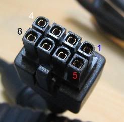
From the pinout of the DA-2, you can see that pins 2-4 carry the +12v and pins 6-8 are the ground, so assuming that when plugged into the 8-pin connector pins 1-4 connect to the yellow wires and pins 5-8 connect to the black wires, you need the yellow wires to go to the Pico's +/white wire and the black wires to go to the Pico's ground/black wire. Probably the easiest way to do this is to cut the barrel connector off the Pico's input wires and solder the respective wires together.
I'm not sure if the DA-2 will even fit into the female end of the 8-pin EPS cable, but assuming it does, you can cut the male end off and solder the 4 yellow wires together and the 4 black wires together.
From the pinout of the DA-2, you can see that pins 2-4 carry the +12v and pins 6-8 are the ground, so assuming that when plugged into the 8-pin connector pins 1-4 connect to the yellow wires and pins 5-8 connect to the black wires, you need the yellow wires to go to the Pico's +/white wire and the black wires to go to the Pico's ground/black wire. Probably the easiest way to do this is to cut the barrel connector off the Pico's input wires and solder the respective wires together.
Just to make sure: So there wouldn't be a problem to solder the top 3 wires to the 1 on the pico psu and all the bottom 4 wires to black wire on the pico?doveman wrote:As far as I can tell, it looks like the 150XT still just uses the black and white leads going to a female barrel connector for power in. The 4pin connector on the Pico is probably a power out to the motherboard.
I'm not sure if the DA-2 will even fit into the female end of the 8-pin EPS cable, but assuming it does, you can cut the male end off and solder the 4 yellow wires together and the 4 black wires together.
From the pinout of the DA-2, you can see that pins 2-4 carry the +12v and pins 6-8 are the ground, so assuming that when plugged into the 8-pin connector pins 1-4 connect to the yellow wires and pins 5-8 connect to the black wires, you need the yellow wires to go to the Pico's +/white wire and the black wires to go to the Pico's ground/black wire. Probably the easiest way to do this is to cut the barrel connector off the Pico's input wires and solder the respective wires together.
Also I looked closer at the EPS connector and the female holes are keyed:
EPS:

vs DA-2:
I could probably shave the pins down on the DA-2 to round them off ---- But, it is probably easier to cut down a ATX extension to a section that fits the keying.
The only possible problem is that the Pico's input wires probably aren't suitable to carry the maximum 12.5amps that the Pico150 could draw. The manual for it says "-Input current should not exceed 8A. For current higher loads, we suggest using a 2x2 mini-FIT JR as an input connector." but you could just unsolder the input wires and replace them with higher rated ones, if you expect to be drawing more than 8A that is.
Thanks for all the info doveman. If you'll let me pick your brain just a bit more....
12v @ 8a is only 96 watts -- so why exactly do they advertise it as 150w?
Also they sell it in bundles with 8.5a brick (I am sure the extra .5a isn't a problem, but still....
I am still semi-clueless-- exactly what kind of wires would I need to carry the load?
Would the wires on an ATX extension carry enough amps? If not how would I terminate those to a DA-2 connector? Or should i just rip up the DA-2 cord and solder directly to that?
You'd have to ask them why they advertise it as 150w, when it's not ready to be used at that power 
Coming out of the ATX extension, you've got 3 wires sharing the 12v load so they can handle it between them. It'll probably be rather difficult soldering the ends of all three wires onto the Pico though, so you might want to get a short bit of cable that's suitable for 12.5amps @ 12v and run that from the Pico to the three wires.
I'm afraid I can't really tell you exactly what cable you want. I couldn't work it out for myself when I needed some and ended up taking the advice of the bloke in the shop. I'm sure I ended up with thicker cable than I needed but it works so I'm happy. However, as there's not a lot of room to solder the cable on to the Pico, you might want to be a bit more careful in choosing your cable and try and get the thinnest you can get away with.
There's a guide to the Load Carrying Capacities of wires by AWG here: http://www.powerstream.com/Wire_Size.htm if it's of any help.
-
ryboto
- Friend of SPCR
- Posts: 1439
- Joined: Tue Dec 14, 2004 4:06 pm
- Location: New Hampshire, US
- Contact:
If you're up to it, you can still use the Pico with systems that need more than 120W. I do. Just let your brick feed any video cards(6-pin pcie power) and the processor(4-pin atx power) directly. This alleviates some of the 12v load on the Pico, and you also don't have to worry about soldering directly to the unit itself.
Doh! How did I forget to mention that, particularly as it's how I've got my system wired, which is sitting on the floor right next to me in an open case 
It's still rather confusing that they state you need to use a different connector/cable if drawing more than 8A/96W, when it's supposedly a 150w device.
It's still rather confusing that they state you need to use a different connector/cable if drawing more than 8A/96W, when it's supposedly a 150w device.