Control: management of fans, temp/rpm monitoring via soft/hardware
Moderators: NeilBlanchard, Ralf Hutter, sthayashi, Lawrence Lee
-
Bobendren
- Posts: 117
- Joined: Sat Aug 06, 2005 7:41 am
- Location: RSA
Post
by Bobendren » Tue Feb 14, 2006 12:59 pm
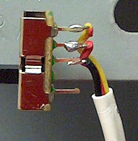
I want to extend the cable and change the switch on the antec tricool i have.
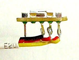
A black, red and yellow wire join the switch to the fan (sleeved in white as seen in the picture below). I thought it might change between voltages to alter the speed but it only gets plugged into the 12v line.
Any ideas? A PWM chip inside the fan's motor maybe? I opened the switch up and couldn't find anything.
This is what it looks like:

-
moritz
- Posts: 167
- Joined: Sat Mar 26, 2005 7:06 am
- Location: Germany
-
Contact:
Post
by moritz » Tue Feb 14, 2006 1:56 pm
I'm sure somebody will be around really soon who knows this stuff better than me, and I'm also sure it's been explained in the forums and probably on the site - but: it's probably some sort of variable inline resistor. That is, it changes the voltage, but not by switching between some input voltages, but by running the 12V through a resistor. See:
http://en.wikipedia.org/wiki/Potentiometer
-
TomZ
- Posts: 386
- Joined: Tue Feb 07, 2006 2:59 pm
Post
by TomZ » Tue Feb 14, 2006 2:06 pm
Based on the cost, I'd bet there are 2 resistors, one for "L" and one for "M." I doubt there would be a PWM controller at that price point.
Open it up, and let's find out!
Or maybe they are enabling or disabling sets of motor windings... You've got me curious now.
-
Bobendren
- Posts: 117
- Joined: Sat Aug 06, 2005 7:41 am
- Location: RSA
Post
by Bobendren » Wed Feb 15, 2006 5:15 am
TomZ wrote:Or maybe they are enabling or disabling sets of motor windings...
That's what my dad reckons.
Basically i just need to know what wires are joined to create the different speeds so i can hook up my own switch.
-
Aleksi
- Friend of SPCR
- Posts: 889
- Joined: Sun Dec 05, 2004 11:34 pm
- Location: Finland -- Folding For SPCR
Post
by Aleksi » Wed Feb 15, 2006 5:57 am
It can be either what Moritz explained, or it can directly effect the switching electronics. Similar to the thermistor in the Globe fans (apparently).
An individual PWM circuit is out simply due to the cost, also altering the coil windings is usually not the easiest way of doing.
-
cpemma
- Posts: 351
- Joined: Sun May 11, 2003 2:31 pm
- Location: S Yorks, OK
-
Contact:
Post
by cpemma » Thu Feb 16, 2006 4:15 pm
Aleksi wrote:An individual PWM circuit is out simply due to the cost...
Hey, that's an £8 fan over here, I've ones half the price with PWM inside.

Main reason for a PWM-style control is the lack of waste heat in a confined space, small transistors, no heat-sink required. It can be done cheaply by delaying the switch-on of the motor coils as the rotor magnet passes by - I'm not saying that's how Antec do it, but using a custom-made IC as Panaflo and others do it works out cheap in bulk.
Bobendren wrote:I opened the switch up and couldn't find anything.
Can you at least tell which wires are joined together in the 3 switch positions, and a photo of the inside?
-
TomZ
- Posts: 386
- Joined: Tue Feb 07, 2006 2:59 pm
Post
by TomZ » Thu Feb 16, 2006 4:54 pm
If someone wants to "donate" a Tri-Cool in the interests of "science," they can send it to me, and I'll dissect it, figure out how it works, and post back here.

-
Bobendren
- Posts: 117
- Joined: Sat Aug 06, 2005 7:41 am
- Location: RSA
Post
by Bobendren » Fri Feb 17, 2006 10:56 am
Can you at least tell which wires are joined together in the 3 switch positions, and a photo of the inside?
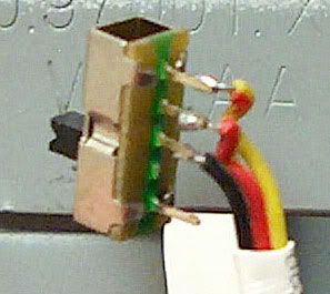
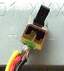
That's actually what i'm asking. I don't want to take the metal off until i find a decent looking switch to replace it with. (i.e i don't want to break it)
Here are some pics of the switch without the platic cover (The switch is in the "Low" position):
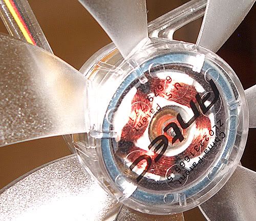
And what one can see of the fan internals:
Last edited by
Bobendren on Fri Feb 17, 2006 11:08 am, edited 1 time in total.
-
TomZ
- Posts: 386
- Joined: Tue Feb 07, 2006 2:59 pm
Post
by TomZ » Fri Feb 17, 2006 11:02 am
What's the patent number on the fan? Maybe we can look that up and get more information.
-
Bobendren
- Posts: 117
- Joined: Sat Aug 06, 2005 7:41 am
- Location: RSA
Post
by Bobendren » Fri Feb 17, 2006 11:52 am
TomZ wrote:What's the patent number on the fan? Maybe we can look that up and get more information.
U.S Patent: 6.679.771
China Patent: ZL02231665.5
Where does one start? Google?
-
TomZ
- Posts: 386
- Joined: Tue Feb 07, 2006 2:59 pm
Post
by TomZ » Fri Feb 17, 2006 12:00 pm
Where does one start? Google?
http://www.uspto.gov/patft/index.html; just search for the patent number.
That patent is related to putting LEDs on a cooling fan. Does that one have LEDs? I didn't think it did.
-
Bobendren
- Posts: 117
- Joined: Sat Aug 06, 2005 7:41 am
- Location: RSA
Post
by Bobendren » Fri Feb 17, 2006 12:15 pm
TomZ wrote:Where does one start? Google?
http://www.uspto.gov/patft/index.html; just search for the patent number.
That patent is related to putting LEDs on a cooling fan. Does that one have LEDs? I didn't think it did.
Yeah it's the LED version.
From the above mentioned site: "The rotational speed of the impeller is controlled by the drive circuitry on the circuit board"
And that means?
"Each LED projects light towards the impeller and to the frame so the light will reflects and bounces all over the fan to produce a fantastic visual effect."
Haha...they tried to be so technical but failed miserably.
"The LEDs can be made to twinkle based on the rotational speed of the fan to increase the visual attractiveness."
I haven't noticed this "increase in visual attractiveness" when increasing the rpm. Maybe it's just me

-
TomZ
- Posts: 386
- Joined: Tue Feb 07, 2006 2:59 pm
Post
by TomZ » Fri Feb 17, 2006 12:17 pm
I haven't noticed this "increase in visual attractiveness" when increasing the rpm.
The didn't say it in the patent, but the visual effect is much better if you blink your eyes rapidly when looking at the fan.

-
Bobendren
- Posts: 117
- Joined: Sat Aug 06, 2005 7:41 am
- Location: RSA
Post
by Bobendren » Fri Feb 17, 2006 2:52 pm
Ok, i got bored and removed the metal thingie.
The inards:
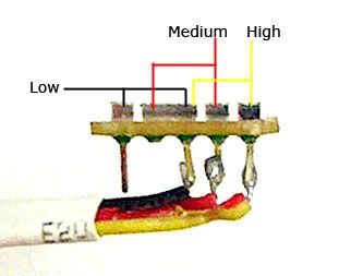
Low: Circuit not closed
Medium: Red and Black
High: Yellow and Black
I don't know if this helps solve the mistery. But at least i know how to connect up a new switch.
-
TomZ
- Posts: 386
- Joined: Tue Feb 07, 2006 2:59 pm
Post
by TomZ » Fri Feb 17, 2006 3:05 pm
My guess is that the fan has 2 resistors in series with the fan.
In low mode, the two resistors in series limit the power to the fan to the "low" level.
In medium mode, one of the resistors is shorted out by the switch, but the other is still in series with the motor, limiting the power to the fan to a "medium" level.
In high mode, both resistors are shorted out by the switch, and the fan runs at "full" power.
I'm pretty sure the above would work, but there are probably other possibilities. 2 resistors are pretty cheap, however, and it's hard for me to believe that there would be a cheaper way to get the job done.
-
nici
- Posts: 3011
- Joined: Thu Dec 16, 2004 8:49 am
- Location: Suomi Finland Perkele
Post
by nici » Sat Feb 18, 2006 2:40 am
TomZ wrote:My guess is that the fan has 2 resistors in series with the fan.
...and it's hard for me to believe that there would be a cheaper way to get the job done.
Both conclusions seem reasonable to me..
It would be very cheap to make and its pretty much fool-proof..
Someone would need to open up the fan hub to make shure though.
-
Laz Winterz
- Posts: 33
- Joined: Tue Oct 18, 2005 8:12 pm
- Location: TX
Post
by Laz Winterz » Sat Sep 30, 2006 3:06 pm
Old topic I know... but I was wondering if it's possible to put the Antec switch on another fan?
-
TomZ
- Posts: 386
- Joined: Tue Feb 07, 2006 2:59 pm
Post
by TomZ » Sat Sep 30, 2006 7:29 pm
Laz Winterz wrote:Old topic I know... but I was wondering if it's possible to put the Antec switch on another fan?
Probably not, because the Antec fan is customized to work specifically with that switch.
