
I drowned my PC in mineral oil 9 months ago. It has worked fine, although it hasn't seen heavy usage. The oil temp gets up to about 120F after about 12 hours of ontime, where it stabilizes (my basement is typically at 65F-70F).
The oil tank (inner tank) was always pretty clean looking, except for the occasional label that came off the PCB or hapless bug that fell in.
However, the water (outer) tank in my double-hull arrangement got really nasty.
First, I believe algae has grown in my tank. Covered everything. Nasty, slimy stuff. Fortunately, it wipes up easily once the tank is emptied.
Second, mineral scale appeared on the glass walls of the aquarium. Probably caused by high concentrations of minerals in the tap water I used. Frequently, I had to refill the water (outer) tank to replace the evaporative losses. But the minerals in our tap water don't evaporate, so I guess the minerals just got more and more concentrated over time, and eventually collected on the sides of the tanks. It took a lot of hard scrubbing with a brillo pad and tile cleaner to get that stuff off.
Third, the metal L-beams had gotten really crusty. Some white stuff covered them. Possibly that is the mineral deposits that collected on the glas, or possibly it is galvanic corrosion. The L-beams was made of one kind of metal, and the nuts&bolts used to attach them to the PVC pipe was a different kind of metal (and they looked pretty clean).
So, I have the follow adjustments to make :
(1) no metal in the water hull, to avoid galvanic activity.
(2) use distilled water only, to avoid mineral accumulation.
(3) find a way to prevent evaporative losses of water, because I don't want to have to keep buying jugs of distilled water. Somehow seal the top?
(4) Find a way to prevent algae from forming in the water. A simple additive should do the trick. Or maybe I can just use bleach or vinegar or something. Dunno.
PC in aquarium full of mineral oil
Moderators: NeilBlanchard, Ralf Hutter, sthayashi, Lawrence Lee
9 months and counting
Last edited by drownmypc on Fri Dec 26, 2008 5:28 am, edited 1 time in total.
medical grade?
Hi, blundell.blundell wrote:which gives me a list of suppliers for the UK, however whenever they ring them they ask what grade mineral oil i want! I dont have a clue, any help?
I'm guessing they wanted to know whether you needed "food grade", "medical grade", or "industrial grade", etc. I don't know precisely what grades there are, but I have a feeling that's what they were getting at. I should think that any grade mineral oil would be fine. Your submerged PCB isn't going to be terribly sensitive to the grade of mineral oil.
The mineral oil I bought was from "Southern States" which is an agricultural supply store here in the southern US. www.animedproducts.com. It is intended as a laxative for farm animals (horses, cows, etc). Says on the label, "Mineral oil is a gentle and effective intestinal lubricant. Mineral Oil aids in normal intestinal evacuation and is not absorbed, is non-fattening and will not increase body temperature. Use one pint for each 120lbs of body weight."
Yeah, okay, they say it is safe but there is no way I'm ever drinking the stuff. It's a petroleum product! And if you should happen to aspirate it (get it into your lungs) there is no known method for removing it, and the body is unable to process it, so it stays there forever. Aspirating mineral oil is bad.
Anyway, I suggest you look for agricultural or veterinary suppliers in the UK. Try using Kelly Search to find something: http://chemicals.kellysearch.co.uk/sear ... l+oil&gcc= or search for "veterinary supply", etc.
-stefan
Last edited by drownmypc on Fri Dec 26, 2008 5:29 am, edited 1 time in total.
xan_user wrote:How hot does the water get? Maybe you just need some high temp loving sucker fish. :lol:
Heh! I doubt any fish can tolerate these temps. The oil temp stabilizes at about 120F after approximately 12 hours of power-on time. Ambient air temp is about 70F, so that's a 50F temp delta.
I think this temp is safe for my machine, but when the water is that hot, it evaporates quickly. It's annoying to have to refill the outer hull. So, I'm looking for a solution to that problem.
evaporative water loss
[Edit: continually updating the table with experimental results]
Well, last night I started an experiment on evaporative water loss -- because, as I mentioned recently, I'm annoyed that I keep having to add water to my outer tank.
I filled two identical glasses with water. Then I added a little bit of mineral oil to one glass. The oil floats on top of the water, making a barrier between the water and the air, about 8mm thick.
Then I weighed both glasses with a postal scale and put them both in front of a fan (a stiff breeze to accelerate evaporation).
Glass A had just water. After a little over nine hours, the water level has visibly dropped in the glass. I measure 23g of evaporative water loss.
Glass B had water+mineral oil barrier. After many hours, no visible drop in water level, and no visible thinning of the oil layer. Sometimes I measure 1 g of weight loss, sometimes not. Since the postal scale I'm using has a 1 gram resolution, I can't be sure that we really have lost a gram of mass. It could just be an artifact of the postal scale's accuracy.
I'll be filling out the table below as the experiment runs.
[Edit -- strange that the evaporation rate would accelerate like this]
One thing is certain -- the layer of mineral oil on top of the water definitely impedes the evaporation of the water.
The questions I still have are:
(1) exactly how fast is the protected water evaporating, if at all?
(2) is any of the oil itself evaporating?
(3) if I dope the water with a bit of vinegar (for algae prevention), how will that affect evaporation? And might the vinegar interfere with the oil's protection of the water? I also wonder whether the vinegar's acidity could weaken the silicone caulking that seals the aquariums.
[Edit: after 4 days, we don't seem to have lost more than a gram of water from the oil-covered glass.]
-stefan
Well, last night I started an experiment on evaporative water loss -- because, as I mentioned recently, I'm annoyed that I keep having to add water to my outer tank.
I filled two identical glasses with water. Then I added a little bit of mineral oil to one glass. The oil floats on top of the water, making a barrier between the water and the air, about 8mm thick.
Then I weighed both glasses with a postal scale and put them both in front of a fan (a stiff breeze to accelerate evaporation).
Glass A had just water. After a little over nine hours, the water level has visibly dropped in the glass. I measure 23g of evaporative water loss.
Glass B had water+mineral oil barrier. After many hours, no visible drop in water level, and no visible thinning of the oil layer. Sometimes I measure 1 g of weight loss, sometimes not. Since the postal scale I'm using has a 1 gram resolution, I can't be sure that we really have lost a gram of mass. It could just be an artifact of the postal scale's accuracy.
I'll be filling out the table below as the experiment runs.
Code: Select all
  Time      Date       Time Elapsed (min)    GlassA (grams)   GlassB (grams)   EvapRateB(mg/min)
------------------------------------------------------------------------------------------------
12:46am, 12/21/2008               0             621              580                n/a
 9:55am, 12/21/2008             549             620              557              41.89
 3:13pm, 12/21/2008             867             621              544              41.52
 6:51pm, 12/21/2008            1085             620              533              43.32
 3:47am, 12/22/2008            1621             621              509              43.80
11:58am, 12/22/2008            2112             621              481              46.88
11:00am, 12/23/2008            3494             620              406              49.80
 7:03pm, 12/23/2008            3977             620              379              50.54
11:34pm, 12/23/2008            4248             620              365              50.61
 2:02pm, 12/24/2008            5116             620              334              48.08
 8:57am, 12/25/2008            6251             620              290              46.39
[Edit -- strange that the evaporation rate would accelerate like this]
One thing is certain -- the layer of mineral oil on top of the water definitely impedes the evaporation of the water.
The questions I still have are:
(1) exactly how fast is the protected water evaporating, if at all?
(2) is any of the oil itself evaporating?
(3) if I dope the water with a bit of vinegar (for algae prevention), how will that affect evaporation? And might the vinegar interfere with the oil's protection of the water? I also wonder whether the vinegar's acidity could weaken the silicone caulking that seals the aquariums.
[Edit: after 4 days, we don't seem to have lost more than a gram of water from the oil-covered glass.]
-stefan
Last edited by drownmypc on Fri Dec 26, 2008 5:45 am, edited 4 times in total.
some answers
The water evap rate is limited by the solubility of the water in the oil: its near 0.
The mineral oil has a very very low evaporation rate at room temperature, I doubt its measurable outside a lab.
Vinegar will not prevent algae, and it will smell nasty. I recommend a few changes to your setup:
1)remove the metal supports from the outer chamber, as you have seen, they corrode in water. You can support teh inner tank on a plastic support or use a bed of aquarium gravel to distribute the Load.
2)Fill the outer tank with a mix of bleach and water, and pour a mineral oil cap over it (use about 1 inch of mineral oil)
That will prevent algae and the oil will prevent evaporation. Just don't spill it.
Better still would be to get a aquarium pump and a radiator and do away with the outer tank entirely.
I looked at putting one of these together a few years ago, for a slightly different purpose: with proper cooling, you could bring such a system down to temps below 0C, with no worries about condensation. With memory, processor, mobo, video card all operating at 0C there is a significant overclocking potential.
I was stopped by the problem of wicking, I never found a good solution and the mess was abysmal. Seeing the successes here I'm tempted to give it another go...thanks for the inspiration!
Re: some answers
Hi, Gambrinus.Gambrinus wrote:The water evap rate is limited by the solubility of the water in the oil: its near 0.
The mineral oil has a very very low evaporation rate at room temperature, I doubt its measurable outside a lab.
Vinegar will not prevent algae, and it will smell nasty. I recommend a few changes to your setup:
1)remove the metal supports from the outer chamber, as you have seen, they corrode in water. You can support teh inner tank on a plastic support or use a bed of aquarium gravel to distribute the Load.
2)Fill the outer tank with a mix of bleach and water, and pour a mineral oil cap over it (use about 1 inch of mineral oil)
That will prevent algae and the oil will prevent evaporation. Just don't spill it.
Better still would be to get a aquarium pump and a radiator and do away with the outer tank entirely.
I looked at putting one of these together a few years ago, for a slightly different purpose: with proper cooling, you could bring such a system down to temps below 0C, with no worries about condensation. With memory, processor, mobo, video card all operating at 0C there is a significant overclocking potential.
I was stopped by the problem of wicking, I never found a good solution and the mess was abysmal. Seeing the successes here I'm tempted to give it another go...thanks for the inspiration!
I was impatient and reassembled my system yesterday, before I could receive any suggestions from knowledgeable SPCR readers. :-(
I replaced the metal spacers with plastic ones -- so, that should take care of the corrosion. It was stupid of me to try using metal in the first place -- I should have known better than that!
I googled around on the web, and found reports that vinegar might eliminate the algae. I'm sorry to hear you report otherwise. I refilled the water tank (5 gallons) and added 1 cup vinegar, and then poured on the mineral oil cap (about a pint, gives me a 15mm layer of oil). I think maybe the oil is containing the vinegar smell, because I smell nothing. Also, I thought maybe the oil would prevent the algae from receiving the air it needs.
If I see algae form, I'll redo the water tank with bleach instead. Thanks for the suggestion!
About the oil cap -- yes, the insolubility of water in oil is exactly what I was counting on. I didn't know how completely insoluble water and oil are, though. My experiment is revealing that it pretty much completely stops evaporation, for all practical purposes.
About using a radiator -- I considered that, but I favor silence over cooling, and my (limited) experience is that water pumps are still audible. Also, I don't know how well the pumps would move the oil (it is less dense, yet more viscous). And finally, I prefer the simplicity of the static water tank -- no tubes, no electricity, no moving parts to fail. If I do a build from scratch, though, I might play with something more complex.
Interesting idea about using cold oil to supercool without condensation. I like it! You'll have to use a different type of oil, though, because mineral oil thickens at lower temps. Just for kicks, I threw a pint bottle of mineral oil in the freezer, and it looked and felt just like vaseline until it warmed up again. I wonder if it can be mixed with something (affordable and non-toxic) to make it thinner at low temps?
About wicking: I have seen others report issues, and for some reason I'm not having a problem with it. I find a very light film of oil on the power supply cables leading to the mobo, but no pooling as reported by others. I do sometimes wonder if oil is accumulating inside the PSU -- I fear I may someday inspect it and dump a bunch of oil onto my shoes. :-)
The keyboard, mouse, audio, and usb cables appear to be oil-free, possibly because (1) the connectors along the top edge of the mobo are actually sitting ABOVE (not immersed in) the oil, and (2) the cables leading from those connectors lead upward about 8 inches which forces the oil to defy gravity a rather long distance. These two factors may possibly slow down the wicking so much that I cannot perceive any happening. Se my post of (Wed Mar 26, 2008 6:28 pm) to get a picture of that.
Did you use mineral oil in your previous attempts, or some other type of oil?
Edit: Scratched original post because I didn't do my homework.
So isn't it possible to fully passively cool by using a larger aquarium and about 40 liters of mineral oil ? That sounds expensive but doable. You could probably do some tricks to either increase surface area (passive radiator?) or you could change bottom, back, and top sides to metal, making you need less mineral oil.
So isn't it possible to fully passively cool by using a larger aquarium and about 40 liters of mineral oil ? That sounds expensive but doable. You could probably do some tricks to either increase surface area (passive radiator?) or you could change bottom, back, and top sides to metal, making you need less mineral oil.
I think so - but maybe a small aquarium with oil will be sufficient. But I haven't even tried that yet, so it is unproven.rill2 wrote: So isn't it possible to fully passively cool by using a larger aquarium and about 40 liters of mineral oil ?
My original motivation for using a double-hull design was to prevent bad oil spills. i was afraid the oil tank might crack or something, so for my first oil system I put the 5-gallon oil aquarium inside an empty 10-gallon aquarium as a fail-safe. That ran way too hot, so I filled the 10-gallon tank with 5 gallons of water, which improved things a great deal: it increased the surface area of our interface to the air, and it increased the thermal mass of the whole system.
A small (5 gallon) tank with only oil will have a relatively small surface area and a relatively small thermal mass. So it seems like it would heat up quickly (small thermal mass) and have trouble transferring heat energy to the air.
But, I'm beginning to believe that the double hull concept is a total bust, because (1) I haven't seen an oil leak after 9 months of operation, so maybe it isn't necessary as a safety precaution, and (2) I suspect the 5-gallon oil tank would more readily transfer its heat to room temperature air than it would to rather warm water.
Another poster gave a convincing argument why the material of the tank is unimportant, provided it is thin enough. I'll try to locate it and give a reference.rill2 wrote: change bottom, back, and top sides to metal, making you need less mineral oil.
Oh, fins! Yes, I certainly agree with you there - glass fins would be harder to make.rill2 wrote:Even if the material doesn't matter, which I'll believe in an instant, can't you get a bigger surface area / volume ratio by finning the metal plates? It sounds a lot easier to get a finned metal plate than a finned glass plate.
In fact, I think maybe the material actually matters with fins. Even setting aside the manufacturability question, I would guess that metal fins would be more effective than glass fins at cooling. That's just a feeling, though. You'd have to either do an experiment, or run some kind of thermal FEA (finite element analysis) simulation.
Also, if thickness matters, you might be able to get away with a plate that is thinner than the aquarium glass. A metal plate can be a lot thinner and have the same strength, right? It seems like changing the back side into finned metal could benefit heat-transfer by a combination of effects.
I don't really fancy changing front or sides into metal, since I'd want to be able to admire the insides. I guess one side glass, one side metal is acceptable if it's really necessary. Bottom plate is possible from aesthetics point of view, but then you might have a problem with circulation. Top is possible, but oil to air directly probably works better than oil-plate-air.
I'm not sure what effort it could take or what it would cost to make an aquarium with the back replaced by a finned metal plate - and I'm not sure exactly how to calculate approximately how much heat you would lose extra if you did that.
How do you calculate how much heat you lose through a single one of those plates? What does it depend on? The material, thickness, surface area, shape, oil temperature, air temperature?
On the topic of lava lamps, you mentioned that it would be necessary to keep a stable temperature inside the aquarium. Is this a hard thing to do for any reason? Does the equilibrium oil temperature fluctuate a lot depending on CPU-load, or does it average out to keep the temperature comparatively stable? Does the surrounding room temperature influence the oil temperature significantly? Are there any random effects that would give unsuitable (for a lava-lamp) fluctuations in temperature?
Even if stable temperature is not a problem, designing a blob-composition that doesn't hurt your electronics, and that has just the right properties to produce the lavalamp effect inside mineral oil of a certain temperature is still a challenge of course.
Edit:
Maybe even impossible.
It might be easiest to just wall off a section of the aquarium and to use a formula that works under whatever the temperature of the mineral oil is. Of course, that would be much less awesome than free-floating blobs, but perhaps still fun. If you wall it off you also prevent the evaporating problem you mentioned might be an issue.
I posted something about thermal transfer in this post: viewtopic.php?p=395902#395902rill2 wrote: How do you calculate how much heat you lose through a single one of those plates? What does it depend on? The material, thickness, surface area, shape, oil temperature, air temperature?
To summarize: H = U * A * T
where U = 6.42 W / m^2 K, A = area in sq meters, T = temp difference in centigrade, and H = heat loss in watts (joules/sec).
In your link to engineeringtoolbox.com (another post) I browsed around and eventually I found the following:
The overall heat transfer coefficient for a wall or heat exchanger can be calculated as:
1 / U A = 1 / h1 A1 + dxw / k A + 1 / h2 A2 (1)
where
U = the overall heat transfer coefficient (W/m2K)
A = the contact area for each fluid side (m2)
k = the thermal conductivity of the material (W/mK)
h = the individual convection heat transfer coefficient for each fluid (W/m2K)
dxw = the wall thickness (m)
I guess now I have to learn about conductivity and convection heat transfer coefficients.
Aluminium has thermal conductivity of about 250, Glass has 1.08, so it seems like aluminium would do a better job at conductive heat transfer than glass. The difference between copper and aluminium (about 400 vs about 250) isn't quite as large as the difference between glass and aluminium, so that may explain why the material doesn't matter as much if the choice is between copper and aluminium. It may matter when it's between aluminium and glass.
I haven't figured out yet how to calculate the convective heat transfer coefficients for mineral oil and air.
I think the wall material is relatively unimportant because the air itself poses a heat transfer bottleneck. Air has poor heat capacity and poor thermal conductivity, hence it is often used for insulation.rill2 wrote:The difference between copper and aluminium (about 400 vs about 250) isn't quite as large as the difference between glass and aluminium, so that may explain why the material doesn't matter as much if the choice is between copper and aluminium. It may matter when it's between aluminium and glass.
An illustrative point: your goose down jacket is mostly using air as an insulator. The goose down itself is not the major barrier to the heat energy transfer. The air itself is the barrier to heat energy transfer. The goose down just keeps the air from mixing within the coat, thus preventing convective heat transfer.
At a microscopic level, a relatively small amount of heat energy transferred from glass to air causes the layer of air adjacent to the glass to quickly reach the same (or almost the same) temperature as the glass. That is due to the low heat capacity of air. When their temps are the same (or similar), the temp gradient is zero (or small), and heat transfer ceases (or slows).
Once that innermost layer of air heats up, it wants to pass its heat energy to the next outer layer of air (which is cooler). But because air has lousy thermal conductivity, that transfer takes place slowly.
Consequently, heat energy moves through air rather slowly, and air becomes a bottleneck.
But, that's all in the absence of mixing -- turbulence or air currents could cause the warm air to mix with cool air and transfer heat more quickly. Hence, the use of goose down in a winter coat to minimize the mixing of the air trapped in the coat's material.
If you use a fan to blow that layer of warm air away, to be constantly replaced by cool (ambient, room temp) air, you can keep cool air air next to the warm glass, thus keeping up the temp gradient, which keeps the heat transfer going. My double-hull tankis passively cooled, but if I point a fan at it, the temp drops by 15F.
My point is this: the thermal conductivity of the glass (or metal or whatever the tank wall is made of) is not the only consideration. You must also consider how readily the oil inside the tank will give up its heat to the tank wall, and how readily the air outside the tank will accept heat energy from the tank wall. I believe that in my case, the air is the bottleneck, unless perhaps a fan is used.
I haven't either! Seems like convective heat transfer would be avery complex subject. I don't know any of the engineering or scientific theory for that.I haven't figured out yet how to calculate the convective heat transfer coefficients for mineral oil and air.
Rill2, I apologize for not looking more closely at the formula you posted here. This equation resembles electrical resistance in parallel and also electrical conductance in series.rill2 wrote: The overall heat transfer coefficient for a wall or heat exchanger can be calculated as:
1 / U A = 1 / h1 A1 + dxw / k A + 1 / h2 A2 (1)
where
U = the overall heat transfer coefficient (W/m2K)
A = the contact area for each fluid side (m2)
k = the thermal conductivity of the material (W/mK)
h = the individual convection heat transfer coefficient for each fluid (W/m2K)
dxw = the wall thickness (m)
Two resistors in parallel, with resistances R1 and R2, have an aggregate resistance R, and are related thus:
1/R = 1/R1 + 1/R2
Alternative view is to consider conductance (inverse of resistance). Resistors can be said to have an electrical conductance, and two resistors in series, with conductances K1 and K2, will have an aggregate conductance
1/K = 1/K1 + 1/K2
Thermal conductance and electrical conductance have mathematical parallels. The aggregate thermal conductance of thermal "resistors" in series has the same formula as for electrical resistors.
The formula you gave is
1 / U A = 1 / h1 A1 + dxw / k A + 1 / h2 A2
This resembles the aggregate conductance of three resistors in series,
1/K = 1/K1 + 1/K2 + 1/K3
where
K = U A = the overall conductance of the oil -> wall -> air pathway
K1 = h1 A1 = conductance of oil while losing heat
K2 = k A / dxw = conductance of tank wall for transferring heat
K3 = h2 A2 = conductance of air while gaining heat
Or, solving for K, we have
K = 1 / ( 1/K1 + 1/K2 + 1/K3 )
So, let's look at that. If K3 is small (the conductance of air), then K (the overall thermal conductance of the system) will be poor, even if the tank wall is very thin and very conductive (i.e. K2 is very big).
This is a kind of mathematical justification for saying that the wall/air interface could be a kind of thermal bottleneck, even if the wall itself is perfectly conductive (made of copper for instance).
But, like you said, we don't know the convective heat transfer coefficient (which is the effective conductance) for air. Or for oil. So we don't know whether those would be bottlenecks or not.
But my gut feeling is that K3 (= h2 A2) is rather large, and dominates the contribution by K2 (= k A / dxw).
it can be calculated if you have the Nusselt number:drownmypc wrote:But, like you said, we don't know the convective heat transfer coefficient (which is the effective conductance) for air
http://www.cheresources.com/convection.shtml#natural
http://www.owlnet.rice.edu/~ceng402/ed1 ... index.html
Wow. That blows me away.jaganath wrote: it can be calculated if you have the Nusselt number:
http://www.cheresources.com/convection.shtml#natural
http://www.owlnet.rice.edu/~ceng402/ed1 ... index.html
add a case?
Hey, thinking about this kind of mod a little bit, it seems like the hard part would be the motherboard mounting. Would it make sense to use something like the Antec Skeleton case, mount everything but the drives, and just drop it in? Admittedly, it would take a tank that's more square, but it could solve some customization headaches. Might look kind of cool. Having the big fan at the top would probably help with the circulation, although it probably depends on the type of radiator/loop thing you might have.
Come to think of it, if you're looking for something that dissipates more heat than glass, I'd think about something I've always wanted to make a case mod with, stone. I wonder how hard it would be to create a cube or something out of granite or marble tiles. You could let the stone heat up, and put a little waterfall on one face to create a water flow to carry the heat off. Now sure, it wouldn't be silent, but it would probably sound more pleasant than a case fan. Well, ok, I'm getting off track here, but there are definitely some possibilities. But turning a computer into a tabletop fountain would be pretty cool, don't you think?
Come to think of it, if you're looking for something that dissipates more heat than glass, I'd think about something I've always wanted to make a case mod with, stone. I wonder how hard it would be to create a cube or something out of granite or marble tiles. You could let the stone heat up, and put a little waterfall on one face to create a water flow to carry the heat off. Now sure, it wouldn't be silent, but it would probably sound more pleasant than a case fan. Well, ok, I'm getting off track here, but there are definitely some possibilities. But turning a computer into a tabletop fountain would be pretty cool, don't you think?
cheapish metal case
Thinking more about putting a system like this in a metal "case" to control the temperature better, one thing I thought of was to use a existing pot, like this:
http://www.kitchensupplydirect.com/114-6500.html
You could probably drop the motheboard in sideways, put the power supply in as well, and if you can find one that's deep enough, you could put the hard drives in the pot on something like a steaming rack held above the oil level. You could also try something like a more rectangular baking pan, if you could find one deep enough. Just a thought.
-
xan_user
- *Lifetime Patron*
- Posts: 2269
- Joined: Sun May 21, 2006 9:09 am
- Location: Northern California.
Re: cheapish metal case
cordis wrote:Thinking more about putting a system like this in a metal "case" to control the temperature better, one thing I thought of was to use a existing pot, like this:
http://www.kitchensupplydirect.com/114-6500.html
You could probably drop the motheboard in sideways, put the power supply in as well, and if you can find one that's deep enough, you could put the hard drives in the pot on something like a steaming rack held above the oil level. You could also try something like a more rectangular baking pan, if you could find one deep enough. Just a thought.

I got sucked in by life for a moment.
I can calculate the whole thing for oil using data I found online, the only problem is still convective heat transfer coefficient for air. "If you know the nusselt number," well, I don't.
Putting the whole thing in aluminium is good for cooling perhaps but it takes a lot of the wow factor out for me. I want to decorate my aquarium and people being able to look inside. I'm only willing to put back, bottom, and sides as metal.
I was hoping just the back side would be enough, so before I start thinking about materials and construction, I would like to calculate how much cooling I get by making the back wall out of, say, a finned plate of aluminium.
The problem is that none of us knows how to calculate it, although we've made progress.
Another option is to fold it in a zig-zag pattern to increase the surfaces facing both oil and air.rill2 wrote:I would like to calculate how much cooling I get by making the back wall out of, say, a finned plate of aluminium.
Start out with a thin plate (or possibly a couple, adding up to) 50cm high and 400cm wide, to get a 2.0 square metres surface. Then fold it sideways back and forth to get your desired case dimensions.
Another very "cool" way to solve the issue would be to find an old housing for a scrapped high power/voltage transformer and use that as a starter. They have cooling fins on the outside and transformer oil on the inside.
Open up one side and cover it with glass if desired, add connectors for all peripherals at the top, and you're ready to roll!
Cheers
Olle
(edited to add pictures and more detailed description)
I've been looking into exactly this strategy these past few months. In fact, I have a rough design for it on google sketchup (a very interesting CADish app). Here's a rendering of it:
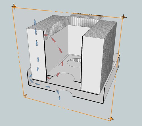
The idea (as you said) is to create an accordion out of the sheet metal, whose folds allow a lot of surface area between the hot oil and cool air. Furthermore, the manifolds (the "accordions") are surrounded by other surfaces to guide air and oil so that they move in parallel counter-flow (opposite directions), which optimizes the heat transfer.
The tank interior holds most of the oil. It's floor has holes cut for two ordinary low speed fans which draw oil from below, pushing oil upward into the tank interior (red arrows). The oil flows upward and over the lip of the interior tank's walls, down into the vanes of the manifold, and all the way down into the chamber below the inner tank, where it gets sucked upward by the fans again.
Meanwhile, there is an exterior framework which moves air past the oil, through the spaces between the vanes, in the opposite direction (parallel counter-flow). Below the lower oil chamber there is an air chamber. A fan pulls the air upward through the air chamber's floor and pushes it upward into the bottom of the vanes. Outer plates (not shown in illustration) keep the air between the vanes as it travels upward, until it exits the channel out the top of the vanes.
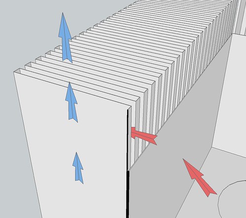
The design has a vane (sort of a hollow fin) every 1/2". The vanes themselves are 1/4" thick (but hollow, for oil to flow within), and spaced 1/4" apart (air flows through these spaces between vanes). I might need to play with that -- maybe give the oil more space and the air less space, to account for their very different viscosities. A quarter inch isn't much space -- I expect the oil and air will be traveling fairly slowly.
I don't know squat about metal work, so I'm planning to take classes at our local shop.
I've also been looking around for aluminum and steel sheeting supply, but it is hard to find thin plates or sheets that are tall enough. Also, they are rather pricey. I've been looking at http://www.mcmaster.com to get a sense of availability and pricing.
We can get 10 ft lengths of 12" wide steel strips for about $40 from McMasters. With 4" vanes, we consume 17 inches of material per inch of manifold length. The 10 feet will fold to about 7 inches of manifold. So, we will need two of these for each 12" manifold. Total cost, about $160.
There is steel at 20 ft lengths and 12-3/8" wide. Spring steel. 0.01 or 0.012 inch thickness. About $100 each. Might be a bit too thin, though. Not sure.
Steel. At 10 foot lengths, 12-3/8" wide, we can get thicker (0.018") wide, about $100 each.
Thicker versions are available in shorter lengths:
.022" in 8' lengths:
.035" in 7' lengths:
Other notes on the design:
The tank interior is 16"x8"x10.5" high.
Volume is 5.8 gallons.
Front manifold (on long side) is 12" (30cm) high, 16" wide, 4" deep.
A vane is an outward-thrusting fold of the tank wall, 1/4 inch thick and extending 4 inches. The vanes are as high as the tank itself, which is 12 inches.
Volume of fluid held by each vane will be 1/4 inch * 4 inches * 12 inches = 12 cubic inches = 0.052 gallons.
There is one vane every 1/2 inch, so along a tank wall 16" wide, there are 32 vanes. All 32 vanes will hold 1.66 gallons.
The long side of the tank is 16" and the short side is 8", for a total of 48" of perimeter, allowing 96 vanes, holding about 5 gallons of mineral oil.
The tank interior requires 5.8 gallons, and the vanes will require 5 gallons, so 10.8 gallons total. That's a lot of oil. Good luck trying to move this thing.
The tank interior footprint is 16"x8", but the 4" vanes all around extends the footprint to 24"x16". That's pretty big.
Normally a 24"x16"x12" tank would have 4 sq ft of surface area on the sides (not counting top and bottom faces). With the 4" vanes at 1/2" spacing, this tank has 8.5x that area, which is 34 sq feet.
-stefan
Olle, you read my mind!Olle P wrote:Another option is to fold it in a zig-zag pattern to increase the surfaces facing both oil and air. Start out with a thin plate (or possibly a couple, adding up to) 50cm high and 400cm wide, to get a 2.0 square metres surface. Then fold it sideways back and forth to get your desired case dimensions.
I've been looking into exactly this strategy these past few months. In fact, I have a rough design for it on google sketchup (a very interesting CADish app). Here's a rendering of it:
The idea (as you said) is to create an accordion out of the sheet metal, whose folds allow a lot of surface area between the hot oil and cool air. Furthermore, the manifolds (the "accordions") are surrounded by other surfaces to guide air and oil so that they move in parallel counter-flow (opposite directions), which optimizes the heat transfer.
The tank interior holds most of the oil. It's floor has holes cut for two ordinary low speed fans which draw oil from below, pushing oil upward into the tank interior (red arrows). The oil flows upward and over the lip of the interior tank's walls, down into the vanes of the manifold, and all the way down into the chamber below the inner tank, where it gets sucked upward by the fans again.
Meanwhile, there is an exterior framework which moves air past the oil, through the spaces between the vanes, in the opposite direction (parallel counter-flow). Below the lower oil chamber there is an air chamber. A fan pulls the air upward through the air chamber's floor and pushes it upward into the bottom of the vanes. Outer plates (not shown in illustration) keep the air between the vanes as it travels upward, until it exits the channel out the top of the vanes.
The design has a vane (sort of a hollow fin) every 1/2". The vanes themselves are 1/4" thick (but hollow, for oil to flow within), and spaced 1/4" apart (air flows through these spaces between vanes). I might need to play with that -- maybe give the oil more space and the air less space, to account for their very different viscosities. A quarter inch isn't much space -- I expect the oil and air will be traveling fairly slowly.
I don't know squat about metal work, so I'm planning to take classes at our local shop.
I've also been looking around for aluminum and steel sheeting supply, but it is hard to find thin plates or sheets that are tall enough. Also, they are rather pricey. I've been looking at http://www.mcmaster.com to get a sense of availability and pricing.
We can get 10 ft lengths of 12" wide steel strips for about $40 from McMasters. With 4" vanes, we consume 17 inches of material per inch of manifold length. The 10 feet will fold to about 7 inches of manifold. So, we will need two of these for each 12" manifold. Total cost, about $160.
There is steel at 20 ft lengths and 12-3/8" wide. Spring steel. 0.01 or 0.012 inch thickness. About $100 each. Might be a bit too thin, though. Not sure.
Steel. At 10 foot lengths, 12-3/8" wide, we can get thicker (0.018") wide, about $100 each.
Thicker versions are available in shorter lengths:
.022" in 8' lengths:
.035" in 7' lengths:
Other notes on the design:
The tank interior is 16"x8"x10.5" high.
Volume is 5.8 gallons.
Front manifold (on long side) is 12" (30cm) high, 16" wide, 4" deep.
A vane is an outward-thrusting fold of the tank wall, 1/4 inch thick and extending 4 inches. The vanes are as high as the tank itself, which is 12 inches.
Volume of fluid held by each vane will be 1/4 inch * 4 inches * 12 inches = 12 cubic inches = 0.052 gallons.
There is one vane every 1/2 inch, so along a tank wall 16" wide, there are 32 vanes. All 32 vanes will hold 1.66 gallons.
The long side of the tank is 16" and the short side is 8", for a total of 48" of perimeter, allowing 96 vanes, holding about 5 gallons of mineral oil.
The tank interior requires 5.8 gallons, and the vanes will require 5 gallons, so 10.8 gallons total. That's a lot of oil. Good luck trying to move this thing.
The tank interior footprint is 16"x8", but the 4" vanes all around extends the footprint to 24"x16". That's pretty big.
Normally a 24"x16"x12" tank would have 4 sq ft of surface area on the sides (not counting top and bottom faces). With the 4" vanes at 1/2" spacing, this tank has 8.5x that area, which is 34 sq feet.
-stefan
Last edited by drownmypc on Mon Mar 02, 2009 5:39 pm, edited 2 times in total.
Evaporative cooling!
Hmm, this is interesting.
I draped a wet cloth over my oil aquarium and pointed a room fan at it.
With the computer on standby (drawing 4 watts, effectively off) the tank oil temp got down to 65.6F / 18.6C.
That's below the room's ambient temp of 70F / 21.1C.
Evaporative cooling!
Nifty.
I draped a wet cloth over my oil aquarium and pointed a room fan at it.
With the computer on standby (drawing 4 watts, effectively off) the tank oil temp got down to 65.6F / 18.6C.
That's below the room's ambient temp of 70F / 21.1C.
Evaporative cooling!
Nifty.
I'd say you don't need to guide the air, but your solution for oil flow management seems great!drownmypc wrote:... the manifolds are surrounded by other surfaces to guide air and oil so that they move in parallel counter-flow (opposite directions), which optimizes the heat transfer.
Your flat vanes have a couple of disadvantages:drownmypc wrote:The design has a vane (sort of a hollow fin) every 1/2". The vanes themselves are 1/4" thick (but hollow, for oil to flow within), and spaced 1/4" apart (air flows through these spaces between vanes). ...
I don't know squat about metal work, so I'm planning to take classes at our local shop.
1) They're probably too thin to get an even oil flow distribution over the surfaces.
2) They're pretty difficult to manufacture.
The solution to both problems is to have the vanes in a simple zig-zag pattern, with at least 1" base width. That's easier to manufacture and the oil flow should be better, reaching all the way out to the edges.
My suggestion is to do a nice blueprint of the design, and let some professional metal shop do the physical work.
Spring steel is definitely the wrong quality. Too hard to work with!drownmypc wrote:Spring steel. ...
These are the thicknesses to go for. .022 should suffice, .035 is very good.drownmypc wrote:Steel. .022" in 8' lengths: .035" in 7' lengths:
... But again: Do see what the professionals say! They have the know-how, the skills, the tools and the material needed.
Personally I think it's too difficult for me as a novice to get the construction sealed at the bottom and at every junction.
Cheers
Olle
Re: Evaporative cooling!
A little followup on this evaporative cooling concept --drownmypc wrote:Evaporative cooling!
I had a 3D game paused for a while, came back and noticed that the tank's oil temp had risen to 55C (131F). Even with a couple small (and quiet-ish) fans pointed at the tank. That was a bit hot for my comfort.
So, I wrapped the tank in a wet cloth. The tank temp dropped to 40C (104F). It took a few hours, of course (after all, it is 5 gallons of oil).
Maybe I'll be able to design the tank to have removable guides, so we'll be able to test that hypothesis. That would be fun. I'm guessing that forced convention will make a significant difference. I predict, um, 10C lower oil temp with forced air versus passive. That's a total SWAG, of course. It's not like I know what I'm doing, or anything. ;-)Olle P wrote:I'd say you don't need to guide the air, but your solution for oil flow management seems great!
Sounds like you know more about metal work than I do, so I can't really dispute your second point.Olle P wrote:Your flat vanes have a couple of disadvantages:
1) They're probably too thin to get an even oil flow distribution over the surfaces.
2) They're pretty difficult to manufacture.
About your first point -- I originally considered a zig-zag pattern. The evolution of my thinking, from start to finish, went like this:
1 - A 12" high, 16" wide flat tank wall has 1.3 sq ft of surface area. Ok.
2 - What about adding fins? A 1" vertical fin spaced every 1/2" along the wall will triple the surface area of the air-tank interface to 4 sq ft! Woot!
3 - Oh, but wait, if the interior of the tank is just a flat wall, it will have just 1.3 sq ft for oil-tank interface. That may be the bottleneck for heat transfer from oil to wall to air.
4 - Fine, so I will put fins on the inside too.
5 - Ick. That's a lot of fins. A lot of welding. Or gluing? They might be breaking off and stuff.
6 - Hmm, fins on the inside and fins on the outside rely on the metal to conduct a lot of heat along it's thin cross section. And if the fin is "wide" - that is, sticks out a long way, like 4 inches instead of just 1 inch, then we need even MORE heat flow through that thin cross section of metal. What metals are heat conductive? Copper rocks. But too expensive. Aluminum is half as conductive as copper. Not so expensive. But hard to weld (so I'm told). Steel has about 1/5th the conductivity of copper. And cheap. And workable (so I hear). Hm. But is it conductive enough for super wide fins? This sounds like a manufacturing nightmare.
7 - Hmm, thicker metal means more heat conductance. So what if I make the fins super thick? Like, maybe 1/8" thick? Actually, what if I make them SUPER thick - like 1" thick and 4" wide? Or go with metal wedges as fins, 1/2" at base, 4" wide, packed along the side of the tank. That's certainly enough metal to conduct the heat along their length. Hmm, but expensive. And heavy. Ridiculously heavy.
8 - Oooh, what if I make the fins HOLLOW! Let the oil flow INSIDE the fins, to supply them with heat. Made how? Hollow out blocks of steel. No, of course not. Buy rectangular tubing and join them together? Hmm, maybe. Then the heat flows transversely THROUGH the hollow fin's metal wall, instead of ALONG the metal. In which case thin metal is GOOD, not BAD. Jeez, how will I avoid leaks after joining all these hollow things together?
9 - Oh, of course, let's just take a big sheet of metal and fold it like an accordion. No joints, no welds, no chances of leaks. The more extreme the folding, the more surface area we get. But two questions: what shape for the folds/vanes, and how closely spaced (how thin), and how wide (how much does a vane "stick out" away from the tank) ?
10 - First, what amount of surface area are we aiming for here? I want extreme surface area -- like about 10x what you'd get with an ordinary tank. Increasing surface area requires either using more closely spaced vanes (and therefore more of them) or using wider vanes (so each vane has more surface area). So, let's consider wide, closely spaced vanes, for lots of surface area.
11 - Now, rectangle or triangle? My feeling is that a triangular cross section with a narrow base will cause oil to flow poorly in the pointy end -- that would be a fair bit of surface area not being given heat. My feeling is that a rectangle, even one with the same "average" thickness as the triangle (that is, half the base width) would do better. That's just intuition though. I can't back that up with real science.
So, I'm trying rectangles, as shown in the design illustration I gave earlier. Unless I cannot manufacture it. I don't know how to do it yet.
I'm doing myself. That's part of the purpose of the project - I do it myself. I WILL learn how to work with metal.Olle P wrote: My suggestion is to do a nice blueprint of the design, and let some professional metal shop do the physical work.
Good to know, and good advice. Thank you!Olle P wrote: Spring steel is definitely the wrong quality. Too hard to work with!
These are the thicknesses to go for. .022 should suffice, .035 is very good.
... But again: Do see what the professionals say! They have the know-how, the skills, the tools and the material needed.
Personally I think it's too difficult for me as a novice to get the construction sealed at the bottom and at every junction.
-
theycallmebruce
- Posts: 292
- Joined: Sat Jul 14, 2007 10:11 am
- Location: Perth, Western Australia